Power supply and wiring – ITT S-DRIVE IM213 User Manual
Page 11
11
Power Supply and Wiring
Section 6
(continued)
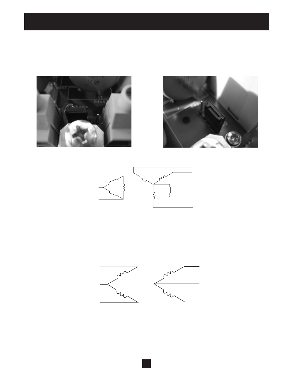
To remove the line to ground MOV protection, locate the jumper shown below. The jumper is located between
the input and output terminal blocks on the main board. Move to the position shown.
For Frame Size 1 Controllers:
For Frame Sizes 2 and 3 Controllers:
Resistance grounding and ground fault protection
Connecting the Wye secondary neutral to ground through a resistor is an acceptable method of grounding.
Under a short circuit secondary condition, any of the output phases to ground will not exceed the normal
line to line voltage. This is within the rating of the MOV input protection devices on the drive. The resistor is
often used to detect ground current by monitoring the associated voltage drop. Since high frequency ground
current can flow through this resistor, care should be taken to properly connect the drive motor leads using
the recommended cables and methods. In some cases, multiple drives on one transformer can produce a
cumulative ground current that can trigger the ground fault interrupt circuit.
Open Delta (consult factory)
This type of configuration is common on 230 volt systems. From time to time it may be encountered where
only single phase power is available and three-phase power is required. The technique uses two single phase
transformers to derive a third phase. When used to power a drive this configuration must be derated to about
70% of the single phase rating of one transformer. This system provides poor regulation and it is possible that
only the two line connected phases will provide power. In this case the drive must be derated to 50 % of its
rating. (Ex. A 20 HP 230 volt drive now becomes a 10 HP 230 volt drive.)