Troubleshooting – ITT S-DRIVE IM213 User Manual
Page 21
21
Troubleshooting
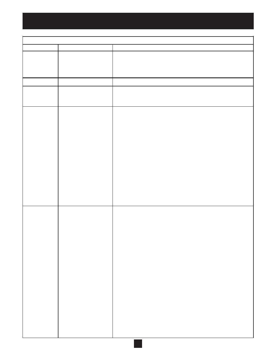
Orange Light Codes
Flashes
Controller Status
Description
Constant
Low Input Voltage
Constant orange light indicates the system input voltage is low. For
230V units, the orange light will be indicated when the input voltage
is between 140Vac and 170Vac. For 460V units, the orange light will
be displayed when the input voltage is between 140Vac and 310Vac.
Red Light Codes
Constant
Controller Error
Internal controller fault. The controller may be internally damaged.
Red
Verify the error by turning power off, waiting 5 minutes then apply
power. If the error persists, replace controller.
2 Blinks
No Water/Loss Of Prime
This fault can be caused by:
• Water supply level in well falls below suction inlet of pump.
• Plugged suction screen.
• Restriction in pipe between pump and pressure sensor.
• Air bound pump.
• Deadheaded pump, pump running against a closed valve.
• Filling long irrigation lines on start-up
• Incorrect setting of Motor Overload Setting switches.
In systems where the motor operates at less than Service Factor
Amps the controller may show a false No Water/Loss of Prime
fault. Reducing the motor overload setting will eliminate the
false readings.
If problem persists, please verify supply capacity.
The controller will automatically restart according to the No Water
Restart Time switches.
3 Blinks
Sensor Fault
This fault can be caused by:
• Disconnected sensor. Disconnect sensor from sensor cable
connector and reconnect to ensure a good connection.
• Disconnected sensor cable lead inside the controller. Check for
loose wires where the sensor cable connects to the circuit board by
tugging on each wire.
• Broken wire in the sensor cable.
• Miswired sensor cable. Check that the wires are connected to the
correct terminals on the control terminal block. Connect terminal
7 (24VDC SUPPLY) to the Brown wire. Connect terminal 6 (TRANSDUCER
INPUT) to the White wire. Connect the drain wire to chassis.
• Failed sensor. To diagnose this failure a meter capable of reading
milliamperes (mA) and DC voltage (VDC) is required.
- Set the meter to read DC voltage (VDC)
- Place the black lead on terminal 5 (COM) and the red lead on
terminal 7 (24VDC SUPPLY)
- If functioning properly, the DC voltage will be 24VDC +/- 15%. If
this voltage is not present, disconnect all control terminals and
repeat the measurement. If voltage does not recover, replace
controller.