13 ramp – Honeywell HC900 User Manual
Page 89
Revision 10
HC900 Hybrid Controller Communications User Guide
81
12/07
6.13 Ramp
Summary
This section contains parameters and addresses for the Ramp.
See the Ramp Register Maps in Table 6-1 for starting and ending addresses (hex) for Ramp #2 through
Ramp #8 Map Addresses.
The Modbus Ramp number address for a Ramp can also be obtained from the Hybrid Control Designer printout
of "Block Modbus Addresses".
Function Code Support:
Reads – Function Code 3
Writes – Function Code 16 (10 hex) for preset of multiple registers (e.g., for floating point)
Writes – Function Code 6 for presetting an integer value
For custom addresses view or print a report in HC Designer.
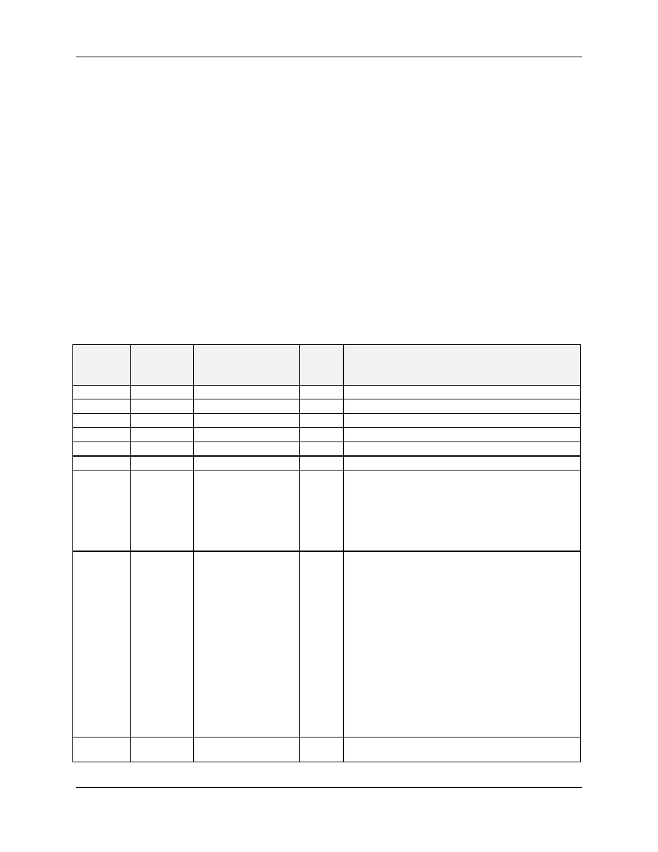
Table 6-23 Ramp Parameters
Fixed
Address
(hex)
Fixed
Register
(decimal)
Parameter Name
Access Notes
6400
25601
PV
R
Floating Point in Engineering Units
6402
25603
Ramp Output
R
Floating Point in Engineering Units
6404
25605
Ramp Default
R
Floating Point in Engineering Units
6406
25607
Ramp Lag Time
R/W
Floating Point in Seconds
6408
25609
Ramp Transfer Up
R/W
Floating Point in Engineering Unit/Second
640A
25611
Ramp Transfer Dn
R/W
Floating Point in Engineering Unit/Second
640C
25613
Ramp #1-4 Enable
R
Bit Packed:
Bit 0: Ramp #1 Enable: 0=NO, 1=YES
Bit 1: Ramp #2 Enable: 0=NO, 1=YES
Bit 2: Ramp #3 Enable: 0=NO, 1=YES
Bit 3: Ramp #4 Enable: 0=NO, 1=YES
Bit 4-15: Unused
640D
25614
Ramp #1-4 Override
Status
R Bit
Packed
Bit 0: Ramp #1 Override Active: 0= NO, 1=YES
Bit 1: Ramp #1 Override to High Limit:
0=Low Limit, 1= High Limit
Bit 2: Ramp #2 Override Active: 0= NO, 1=YES
Bit 3: Ramp #2 Override to High Limit:
0=Low Limit, 1= High Limit
Bit 4: Ramp #3 Override Active: 0= NO, 1=YES
Bit 5: Ramp #3 Override to High Limit:
0=Low Limit, 1= High Limit
Bit 6: Ramp #4 Override Active: 0= NO, 1=YES
Bit 7: Ramp #4 Override to High Limit:
0=Low Limit, 1= High Limit
Bit 8-15: Unused
640E
25615
Ramp #1 Output
Scale High
R/W
Floating Point in Engineering Units