Honeywell HC900 User Manual
Page 41
Modbus/TCP & Modbus RTU Function Codes
Function Code 04 - Read Input Registers
Revision 10
HC900 Hybrid Controller Communications User Guide
33
12/07
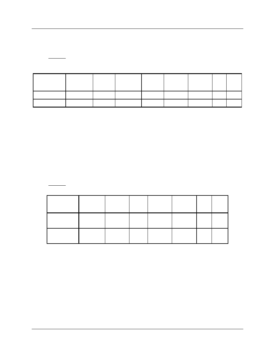
Query
The query message specifies the starting register and quantity of registers to be read. Registers are
addressed starting at zero: registers 1-16 are addressed as 0-15.
Example: Read analog inputs #1 and #2 (Rack #1, Module #1) addresses 0-3, as floating point values from
the controller at slave address 1.
Query message format for function code 04
Slave
Address
(00 for TCP)
Function
Code
Starting
Address
High
Starting
Address
Low
Number
Addresses
High
Number
Addresses
Low
CRC
(RTU)
CRC
(RTU)
TCP
Example
00 04 00 00 00 04
RTU
Example
01 04 00 00 00 04
CRC
CRC
Response
The register data in the response message is packed as two bytes per register. For each register, the first
byte contains the high order bits and the second contains the low order bits.
The floating point values require two consecutive registers. The byte order of the floating point number is
determined by the setting of the byte swap configuration value. In this example, and the examples that
follow, the byte swap order is FP B. Refer to subsection 1.3. The first 16 bits of the response contain the
IEEE MSB of the float value. The second 16 bits of the response contain the IEEE LSB of the float value.
If the master station requests only one register at an address of a floating point value, then half of a float
will be returned.
The Modbus RTU protocol has a single byte count for function code 04, therefore the Modbus RTU
protocol can only process up to 63 floating point values in a single request.
Example: Analog inputs #1 and #2 as floating point values where AI #1 = 100.0 and AI #2 =55.32
Response message format for function codes 04
Slave
Address
(00 for TCP)
Function
Code
Byte
Count
Data Data
CRC
(RTU)
CRC
(RTU)
TCP Example
00
04
08
42 C8 00 00
(100)
42 5D 47 AE
(55.32)
RTU Example
01
04
08
42 C8 00 00
(100)
42 5D 47 AE
(55.32)
CRC CRC