5 function code 03- read holding (data) registers – Honeywell HC900 User Manual
Page 38
30
HC900 Hybrid Controller Communications User Guide
Revision 10
12/07
4.5 Function Code 03- Read Holding (Data) Registers
Description
Function code 03 (also referred to as 4X decimal references) is used to read 32-bit floating point, 32-bit
unsigned/signed integer and 16 bit integer data in the controller as described in Section 6. Registers are
consecutive.
In pre-4.0 configurations only it is also used to Read certain analog input modules for commonality of
UMC800 controller addresses. This applies to analog input modules positioned ONLY in the first 8 Slots
of Rack #1, providing support ONLY for the first 64 channels. Use Function Code 04 to address all
analog inputs in the HC900 controller.
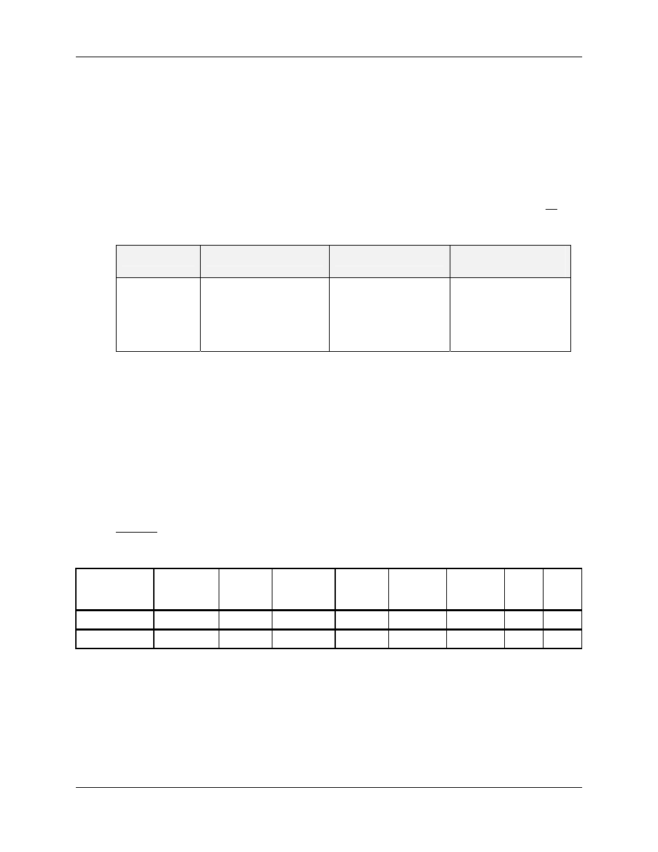
Table 4-8 HC900 AI Address Mapping supported by Function Code 03
Rack
Channel
Register Range
Hex
Address Range
1
1 - 64
65 - 128
1 - 127
65 - 255
0 -7F
(uses register
addressing 1800 -
187Fh)
Not Supported
If a request is made to an address that does not exist in the map in Section 6 , the controller will honor that
request and return zeros for that address. This behavior will greatly enhance the bandwidth on the link vs.
making several different requests for non-contiguous data elements. (i.e. Consider a controller that is
configured for AI #1 and AI #3 and for some reason AI #2 is an invalid request.) The contiguous method
would allow the read of AI #1 through AI #3 and the data location for AI #2 would be zeros.
Broadcast is not supported.
Query
The query message specifies the starting register and quantity of registers to be read. Registers are
addressed starting at zero: registers 1-16 are addressed as 0-15.
Example: Read PV, Remote SP, Working SP, and Output as floating point values for Loop #1 in the
controller at slave address 1.
Query message format for function code 03
Slave
Address
(00 for TCP)
Function
Code
Starting
Address
High
Starting
Address
Low
Number
Addresses
High
Number
Addresses
Low
CRC
(RTU)
CRC
(RTU)
TCP
Example
00 03 00 40 00 08
RTU
Example
01 03 00 40 00 08
CRC
CRC
Response
The register data in the response message is packed as two bytes per register. For each register, the first
byte contains the high order bits and the second contains the low order bits.
The floating point values require two consecutive registers. The byte order of the floating point number is
determined by the setting of the byte swap configuration value. In this example, and the examples that
follow, the byte swap order is FP B. Refer to page 10. The first 16 bits of the response contain the IEEE
MSB of the float value. The second 16 bits of the response contain the IEEE LSB of the float value. If the