Figure 4-5. analog reference calibration window, Analog reference calibration window -9, R. 4.4.3 – KEPCO KLR Series User Manual User Manual
Page 87
KLR 091313
4-9
5. Click the Press to ACCEPT button to accept the value; the status display now reads OUTC.
At the ANALOG I/O PORT J2, connect the DVM to CURR_RBACK and GND as shown in
Figure 4-1. Click the “+” button to increase and the “–“ to decrease the output current until
the DVM reads as close as possible to 10V.
6. Click the PRESS TO ACCEPT button to accept the value. The status display will not change.
Click the ANALOG REF button on the calibration window to proceed to external calibration
(see PAR. 4.4.3).
4.4.3
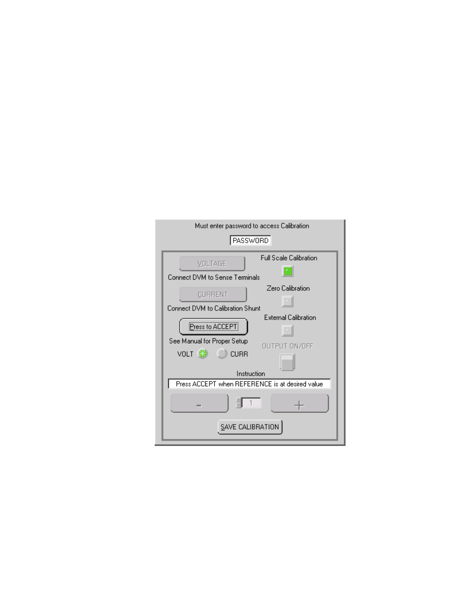
ANALOG REFERENCE CALIBRATION (VXI plug&play DEMO)
During analog reference calibration the external analog reference voltages used to establish full
scale output current and voltage are calibrated.
1. Click the ANALOG REF button on the Calibration Window; the Analog Reference Calibration
Window (Figure 4-5) appears and the status display on the VXI main panel reads INPV. With
the reference voltage adjusted to 10.000V, click the PRESS TO ACCEPT button to accept
the value.
FIGURE 4-5. ANALOG REFERENCE CALIBRATION WINDOW
2. The status display reads INPC. With the reference voltage adjusted to 10.000V, click the
PRESS TO ACCEPT button to accept the value.
3. The status display will not change. Proceed to PAR. 4.4.4 to exit calibration.