1 programming with external resistance, Programming with external resistance -36, 14 analog programming of output voltage or – KEPCO KLR Series User Manual User Manual
Page 76: Current using resistance -36, Ar. 3.4.1), 1 for r, D 3.4.1 for
3-36
KLR091313
Refer to PAR 3.2.6 for enabling/disabling the output using Remote Inhibit. Refer to PAR. 3.2.2
for instructions on exiting Analog Remote mode.
The remaining functions present at the Analog I/O Port connector, including the fault relay
(RELAY_NO, RELAY_NC, RELAY_COM) and external trigger (EXT_TRG), remain active for all
operating modes.
3.4.1
PROGRAMMING WITH EXTERNAL RESISTANCE
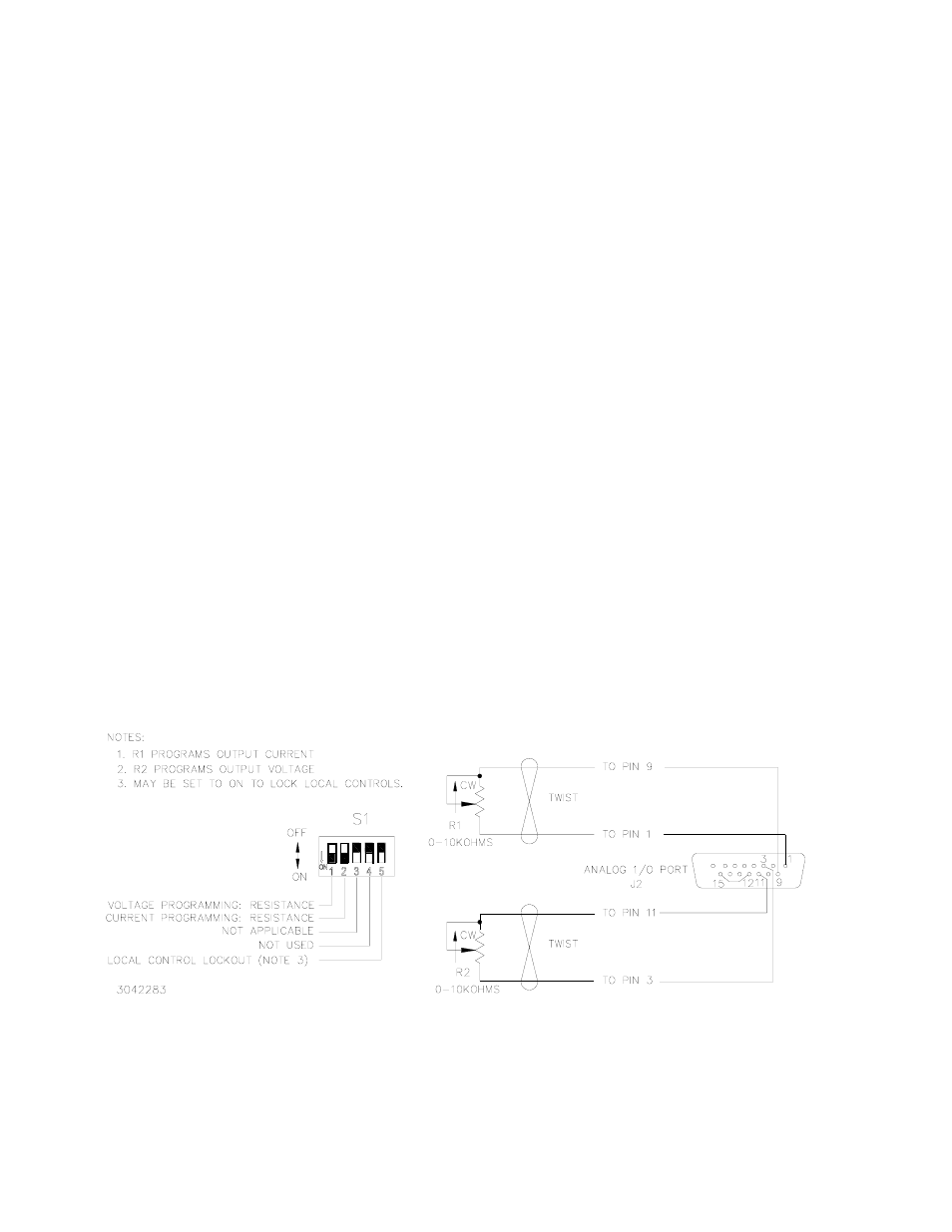
Figure 3-14 is a simplified diagrams of the KLR showing the switch configuration and external
connections required for analog programming using an external resistance.
1. Limit model (PAR. 3.2.9) and Overvoltage and Overcurrent settings (PAR 3.4.3) must be
established via either local programming or digital remote programming prior to initiating
Analog Remote programming.
2. Turn off power and configure the Analog I/O DIP switch (Figure 2-2) as follows:
SW1: ON (Program output voltage via resistance)
SW2: ON (Program output current via resistance)
SW3: either OFF or ON (disabled when in remote analog programming mode; see
Table 2-2)
SW4: Reserved - Do not use.
SW5: Either OFF (Local controls enabled) or ON (Local controls locked)
3. Configure Analog I/O Port J2 (Figure 2-2) by referring to Table 2-7 and Figure 3-14 (ground-
ing J1 pin 12 enables analog programming).
FIGURE 3-14. ANALOG PROGRAMMING OF OUTPUT VOLTAGE OR
CURRENT USING RESISTANCE