Control input terminal block assignments -5, Analog i/o connector (j2) pin assignments -5 – KEPCO KLR Series User Manual User Manual
Page 29
KLR 091313
2-5
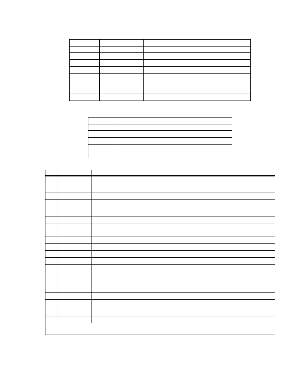
TABLE 2-5. LAN PORT CONNECTOR (J7) PIN ASSIGNMENTS [E-SERIES MODELS ONLY]
PIN
SIGNAL NAME
FUNCTION
1
TX+
Transmit +
2
TX–
Transmit –
3
NOT USED
4
NOT USED
5
NOT USED
6
NOT USED
7
RX+
Receive +
8
RX–
Receive –
TABLE 2-6. CONTROL INPUT TERMINAL BLOCK ASSIGNMENTS
TERMINAL
FUNCTION
M+
Positive output monitor connection (TB5) (see PAR. 2.7.5.1)
S+
Positive sense connection (TB4) (see PAR. 2.7.5.1)
CS
Current Share bus (TB3) (see PAR. 2.7.7.1)
S-
Negative sense connection (TB2) (see PAR. 2.7.5.1)
M-
Negative output monitor connection (TB1) (see PAR. 2.7.5.1)
TABLE 2-7. ANALOG I/O CONNECTOR (J2) PIN ASSIGNMENTS
PIN
SIGNAL NAME
FUNCTION
1
Cref
Analog signal which programs output current from zero to full scale. Voltage or resistance programming
is selected via DIP switch position 2 (See Table 2-2). Refer to PAR. 3.4.2 for voltage programming and
3.4.1 for resistance programming.
2
RELAY_NO
Connected to RELAY_COM (pin 4) for relay energized condition. (1)
3
Vref
Analog signal which programs output voltage from zero to full scale. Voltage or resistance program-
ming is selected via DIP switch position 1 (See Table 2-2). Refer to PAR. 3.4.2 for voltage programming
and 3.4.1 for resistance programming.
4
RELAY_COM
Relay common. (1)
5
Reserved.
6
VOLT_RBACK
Analog signal which represents output voltage from zero to full scale (see PAR. 3.4).
7
CURR_RBACK
Analog signal which represents output current from zero to full scale (see PAR. 3.4).
8
REM_INH
Allows single signal to control output on/off. See PAR. 3.2.6.
9
GND
Ground
(2)
10
RELAY_NC
Connected to RELAY_COM (pin 4) for relay not energized condition (1)
11
GND
Ground
12
ANALOG_CTRL
Enables or disables analog programming (see PAR. 3.4).
1 = Analog programming disabled (default, no connection)
0 = Analog programming accepted (use jumper on mating connector to connect to pin 9, 11, 13 or 15
(ground).
13
GND
Ground
14
EXT_TRG
Performs same function as SCPI *TRG command if unit is programmed for external triggering via digital
remote mode. Transition from 1 (+5V) to 0 (ground) causes values established by VOLT:TRIG and
CURR:TRIG commands to become unit setpoints (see PAR 3.3.2, External Triggering).
15
GND
Ground
(1) Refer to PAR. 3.2.17.1 to configure internal relay.
(2) All GND connections are common.