Section 2 - installation, 1 unpacking and inspection, 2 terminations and controls – KEPCO KLR Series User Manual User Manual
Page 25: 1 front panel controls and indicators, Table 2-1. controls, and indicators, Unpacking and inspection -1, Terminations and controls -1, Front panel controls and indicators -1, Klr series, front panel controls and indicators -1, Controls, and indicators -1
KLR 091313
2-1
SECTION 2 - INSTALLATION
2.1
UNPACKING AND INSPECTION
This instrument has been thoroughly inspected and tested prior to packing and is ready for
operation. After careful unpacking, inspect for shipping damage before attempting to operate.
Perform the preliminary operational check as outlined in PAR 2.5. If any indication of damage is
found, file an immediate claim with the responsible transport service.
2.2
TERMINATIONS AND CONTROLS
2.2.1
FRONT PANEL CONTROLS AND INDICATORS. Refer to Figure 2-1 and Table 2-1.
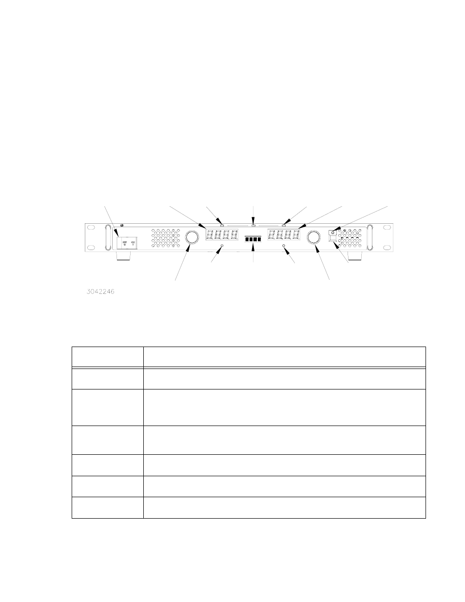
FIGURE 2-1. KLR SERIES, FRONT PANEL CONTROLS AND INDICATORS
TABLE 2-1. CONTROLS, AND INDICATORS
CONTROL OR
INDICATOR
FUNCTION
POWER ON/OFF
Circuit Breaker
Turns the power supply on or off. Applies input power to power supply internal circuits. Circuit breaker
provides input overload protection.
VOLTAGE
control/switch
Multifunction rotary encoder with momentary-contact pushbutton switch. Rotate to set output voltage
(PAR. 3.2.10) and overvoltage limit (PAR. 3.2.11). Also used to enter SET mode of voltage program-
ming (PAR. 3.2.10.2), change GPIB address (PAR. 3.2.12), change RS 232 baud rate (PAR. 3.2.13),
and enter calibration password and perform calibration (PAR. 4.3).
DC VOLTS
display
Four-digit LED display that shows voltage settings:
a. Shows actual output voltage (default).
b. Shows voltage set point (PAR. 3.2.10.2) or overvoltage limit when function selected (PAR. 3.2.11).
CV
indicator
Green LED lights to indicate power supply is operating in constant voltage mode (see PAR. 3.2.10).
Status
4 character display
Displays active function or blinks for error messages. Normally blank (VOLTAGE and CURRENT
LEDs display actual voltage and current).
CC
indicator
Amber LED lights to indicate power supply is operating in constant current mode (see PAR. 3.2.10).
POWER ON/OFF
Circuit Breaker
VOLTAGE
control/momentary switch
DC VOLTS
display
CV
indicator
Status
display
CC
indicator
DC AMPERES
display
CURRENT
control/momentary switch
DC OUTPUT
indicator
DC OUTPUT
on/off switch
PROTECT
momentary switch
LAN
indicator
[E-Series models only]
FUNCTION
momentary switch