Figure 3-12. adding multiple steps (ramps) to list, 6 setting limit model [e-series models only, Setting limit model [e-series models only] -34 – KEPCO KLR Series User Manual User Manual
Page 74: 12 adding multiple steps (ramps) to list -34
3-34
KLR091313
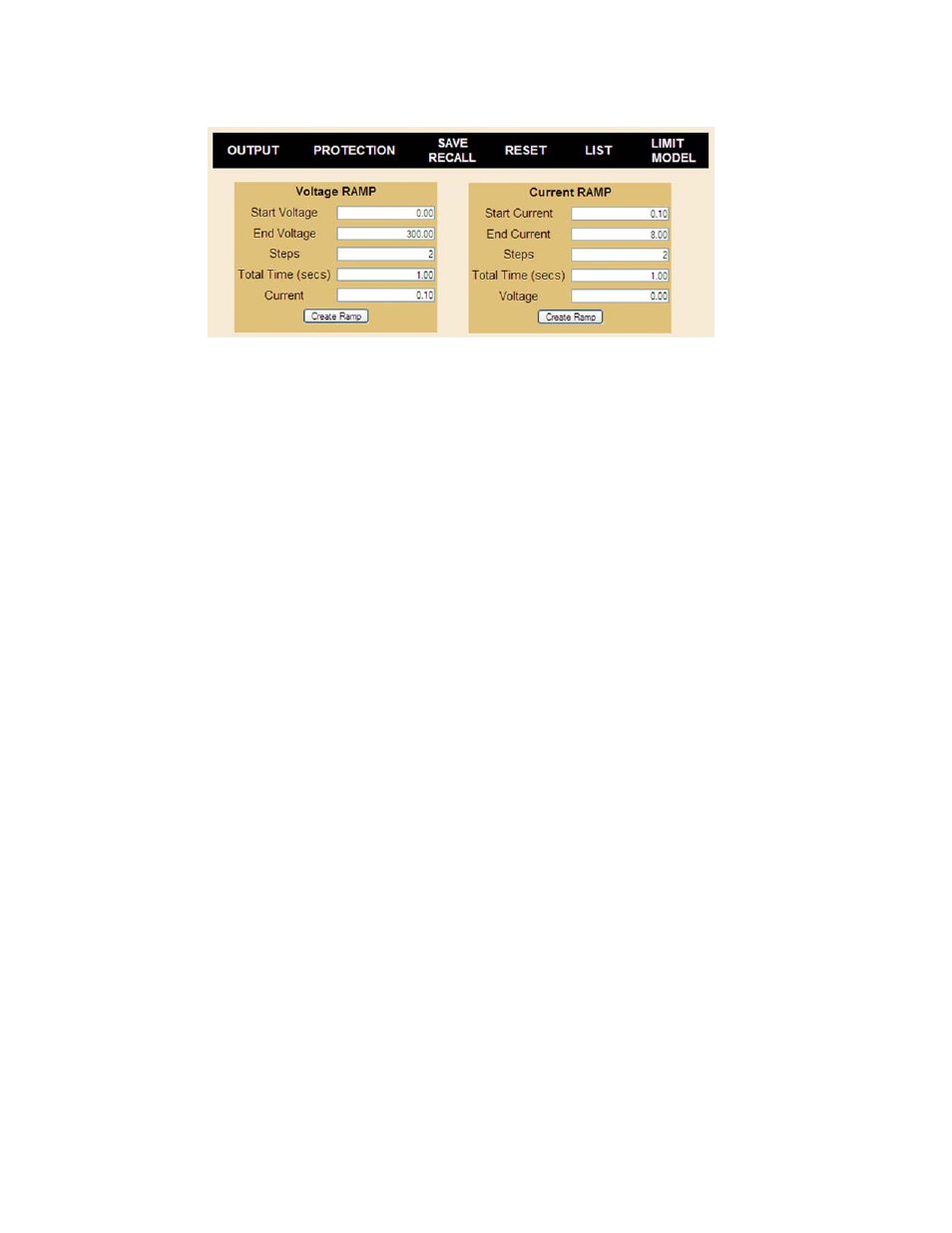
FIGURE 3-12. ADDING MULTIPLE STEPS (RAMPS) TO LIST
Execute the List. Steps may be added to a list using Add to List, Current Ramp or Voltage
Ramp buttons, however the total number of steps can not exceed 100. To execute the list, enter
the number of times the list is to be executed in the Loops box (1 to 65536; 0 is continuous
looping), set the output on (click the On/Off button if necessary) and click the Execute List but-
ton. While the list is running, the title of the Execute List button changes to Stop Execution.
After the completion of the specified number of LIST cycles, the output stabilizes at the condi-
tions in the last LIST step.
Stop the List. If the Stop Execution button is clicked to stop the list, the output stays on with
the voltage and current at the list values prior to the stop command, and the Stop Execution
button reverts to Execute List. If the Execute List button is clicked again, the list restarts from
the beginning. If the list is stopped by clicking the *RST button, the output turns off and Output
setpoints are reset to 0V, minimum current, except that if last setting recall (PAR. 3.2.10.3) is
enabled, the Setpoint values are from the last setting.
3.3.6.6.6 SETTING LIMIT MODEL [E-SERIES MODELS ONLY]
Refer to PAR. 3.2.9 for details about what Limit Model means for KLR and how the limit model
affects other parameters. Click LIMIT MODEL (Figure 3-7) to open the Limit Model dialog box
(Figure 3-13). The current limit model settings are displayed. To change the settings enter the
Unit Password (see PAR. 3.2.8) and press ENTER key on the computer keyboard. After the
password is accepted, the Unit Password field is inaccessible (gray) and the Maximum Voltage
and Maximum Current fields can be changed. Enter the desired maximum voltage and maxi-
mum current, then press ENTER key; all fields are gray for a second or two while the power
supply accepts each entry. The Password field is reset after leaving the Limit Model dialog box.
Setting a new limit model resets the setpoints to zero Volts and minimum Amperes and resets
the OVP and OCP values to 120% of limit model maximum. A minimum programmed current is
required to ensure proper operation of the power supply under all load conditions. Programmed
current is automatically set to be at least the minimum current (actual value depends on model,
see Table 1-2). If DIP switch position 3 is enabled (see Table 2-2 and PAR. 3.2.10.3), stored set-
points for voltage and current are cleared when the limit model settings are saved.