Section 3 - operation, 1 standard power supply operation, local control, 1 general – KEPCO JQE 150-1.5MVPY-26956 Half Rack User Manual
Page 25: 2 load connection, 1 local error sensing, 2 remote error sensing, Standard power supply operation, local control -1, General -1, Load connection -1, Local error sensing -1
JQE SPECIAL SVC 081111
3-1
SECTION 3 - OPERATION
3.1
STANDARD POWER SUPPLY OPERATION, LOCAL CONTROL
3.1.1
GENERAL
The Power Supply is shipped from the factory with three (3) removable jumper links in place at
the rear barrier strip TB501 as shown in FIG. 3-1, as well as a link between REF and RPC1 ter-
minals of rear barrier strip TB502 that enables the front panel CURRENT LIMIT “B” control.
THESE LINKS MUST BE IN PLACE AND SECURED TIGHTLY for standard local operation.
Loose terminal links or wires at the barrier strip will cause malfunction of the power supply.
3.2
LOAD CONNECTION
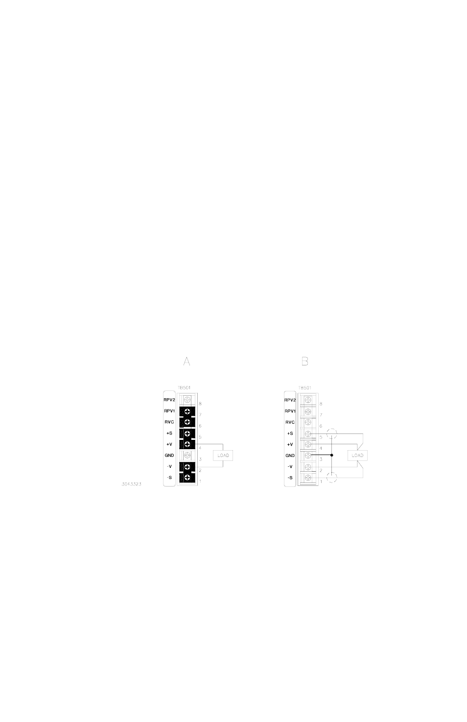
The load may be connected in either of the two ways illustrated (Figure 3-1).
3.2.1
LOCAL ERROR SENSING (SEE FIGURE 3-1A.)
This type of load connection is recommended for constant load applications. Install the links
between +S and +V terminals and between –S and –V terminals of TB501 at the rear panel.
Load connecting wires should be as heavy as practicable, since load wire voltage drops will
degrade regulation performance. Twisting of load wires will help to preserve the low output
impedance as well as reduce the coupled and radiated noise of the power supply.
FIGURE 3-1. LOAD CONNECTION SHOWING A FLOATING LOAD
3.2.2
REMOTE ERROR SENSING (SEE FIGURE 3-1B.)
Remove the links between +S and +V terminals and between –S and –V terminals of TB501 at
the rear panel. Specified regulation performance DIRECTLY AT THE LOAD requires the use of
LOAD CONNECTION,
DEFAULT JUMPER LINKS INSTALLED,
WITHOUT REMOTE ERROR SENSING
LOAD CONNECTION
WITH REMOTE ERROR SENSING
(KELVIN CONNECTION)