2 current limit control channel, Table 1-3. current limit values, 3 current monitor – KEPCO JQE 150-1.5MVPY-26956 Half Rack User Manual
Page 14: Current limit control channel -4, Current monitor -4, Current limit values -4
1-4
JQE 26956 081111
NOTE: The default ZERO voltage calibration done at the factory is for local control. Because
the front panel voltage control potentiometer has a value higher that zero (usually
0.05% of the nominal value of the potentiometer) when set to the full counterclockwise
position, the ZERO calibration is inaccurate if the remote control resistor reaches a
perfect zero. Therefore, when operating with a remote control resistor in voltage mode,
it is recommended that the ZERO and FULL SCALE adjustments be recalibrated (see
PAR 4.5.2.2. and 4.5.5).
c) REMOTE ERROR SENSING: Rear terminals provide for connection of error sensing
leads directly at the load. The four-terminal load connection compensates for the voltage
drop along the load wires. Up to 0.5 Volt per load wire can be compensated using
remote sensing.
1.7.2
CURRENT LIMIT CONTROL CHANNEL
a) LOCAL OUTPUT CURRENT LIMIT CONTROL “A”: 10-turn precision potentiometer at
the front panel, controls the current limit from less than 10% to 100% of the rated output
current (I
O
) (see Table 1-3). Current control “A” accuracy is 0.5% of I
O
nominal.
a) LOCAL AND REMOTE OUTPUT CURRENT LIMIT CONTROL “B”: A 10-turn precision
potentiometer at the front panel controls the current limit from 1% to 105% of the nominal
“B” value (see Table 1-3). Current control “B” accuracy is 0.5% of the nominal “B” value.
When Current Limit “B” is active, if the unit is operating in current limit mode, the lowest
value of current limit “A” and “B” functions as the current limit for the unit. Current control
“B” is enabled by the link installed on the rear panel terminal block TB502 between pin 1
(REF) and pin 2 (RPC1); if this link is removed, only current control “A” is active.
When Current Limit “B” is active, remote resistive control is possible by connecting an
external variable resistance between terminal 2 (RPC1) and terminal 3 (RPC2) of
TB502. The external resistance will be in parallel with the 500 Ohm front panel LIMIT “B”
potentiometer. A zero ohm external resistance will reduce current limit “B” to approxi-
mately 1% of the nominal “B” value. The adjustment curve is non-linear, proportional to:
where
R
ext
is the external resistive control value in Ohms
R
int
is the front panel Current Limit Control “B” value (500 Ohms nominal value for full
clockwise positon.
1.7.3
CURRENT MONITOR
A current monitor voltage output is available to externally monitor output current. This output
signal is available at rear terminal block TB503 across terminals 1 (+C MON) and 2 (–C MON).
The transfer factor of the current monitor signal is 50mV/A. Both ZERO and FS calibrations for
the Current Monitor signal are provided.
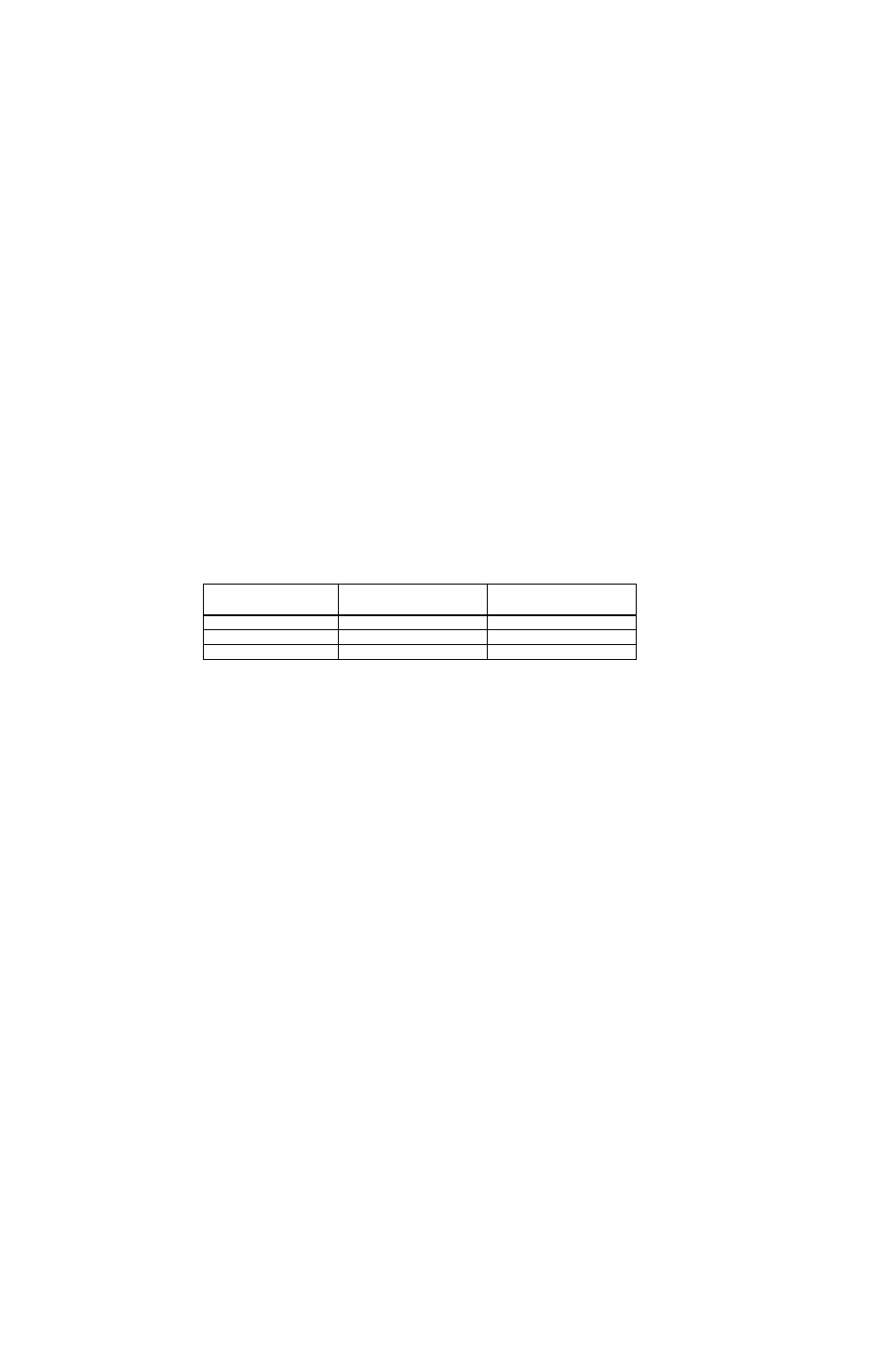
TABLE 1-3. CURRENT LIMIT VALUES
MODEL
CURRENT LIMIT “A”
NOMINAL VALUE
(AMPS)
CURRENT LIMIT “B”
NOMINAL VALUE
(AMPS)
JQE 15-12MVPY-26954
5
4.3
JQE 55-5MVPY-26955
5
2.7
JQE 150-1.5MVPY-26956
1.5
0.4
5
Rint
(
) R
ext
(
)
Rint Rext
+
---------------------------------
+