Chapter 4 function overview, Chapter 4 function overview -1 – RIGOL DSA875 User Manual
Page 33
RIGOL
User’s Guide for EMI Test System
4-1
Chapter 4 Function Overview
Users can perform conduction and radiation tests using EMI Test System and
RIGOL DSA series spectrum analyzer. You can measure the interference voltage
on the power cable using the linear impedance stability network (LISN) and
perform amplitude correction on the results by loading the correction factor
(antenna, cable, other or user) automatically in the radiation test.
This software also provides various functions to facilitate your measurements. You
can set various parameters (such as the frequency range, resolution bandwidth
and scan time) via the scan list. After performing a scan, the results can be
displayed in log or linear format. You can search for signal, measure its peak value,
quasi-peak value and average as well as display the results in the peak list. You can
mark and delete the undesired signal as well as easily recognize signals that do not
pass the standard limit line by using the peak list function.
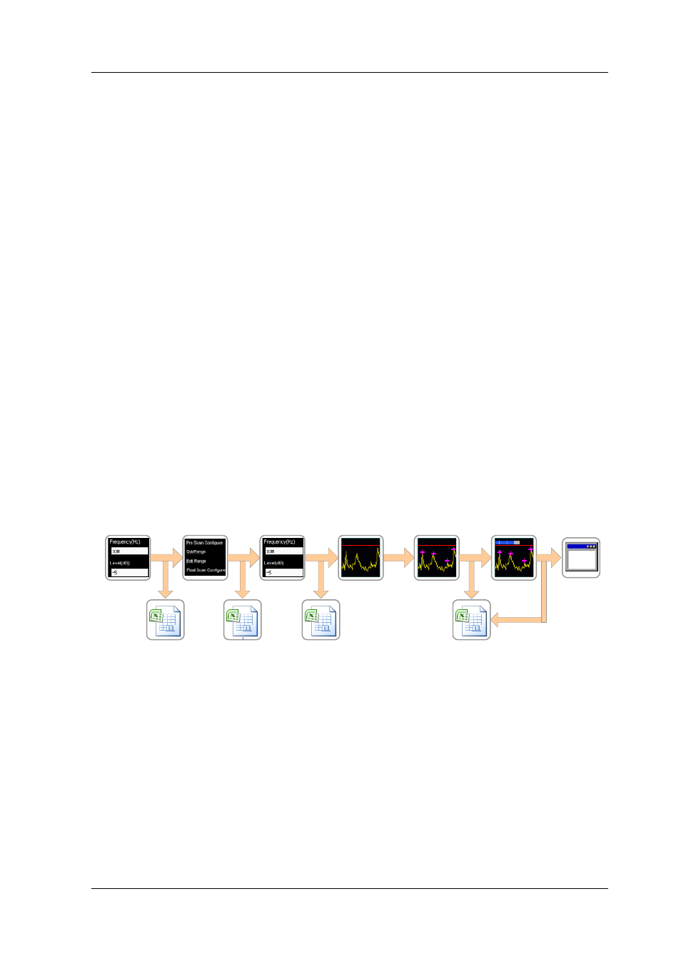
For users to use the software to quickly perform EMI test, the measurement
procedures as shown in the figure below are recommended.
Edit the
limit line
Peak
search
Final
scan
Set the scan
parameters
Correction list
(*.csv)
Scan list
(*.csv)
Pre- scan
Peak list
(*.csv)
Limit line list
(*.csv)
Edit the amplitude
correction data
Test report
(*.html)
Figure 4-1 Function Overview
1. Edit the amplitude correction data:
Enter amplitude correction setting and compensate the gain or loss of the
external devices (such as the antenna and cable). You can view the correction
data list in table form as well as save and load the correction data currently
edited.