Chapter 3 interface layout, Chapter 3 interface layout -1 – RIGOL DSA875 User Manual
Page 29
RIGOL
User’s Guide for EMI Test System
3-1
Chapter 3 Interface Layout
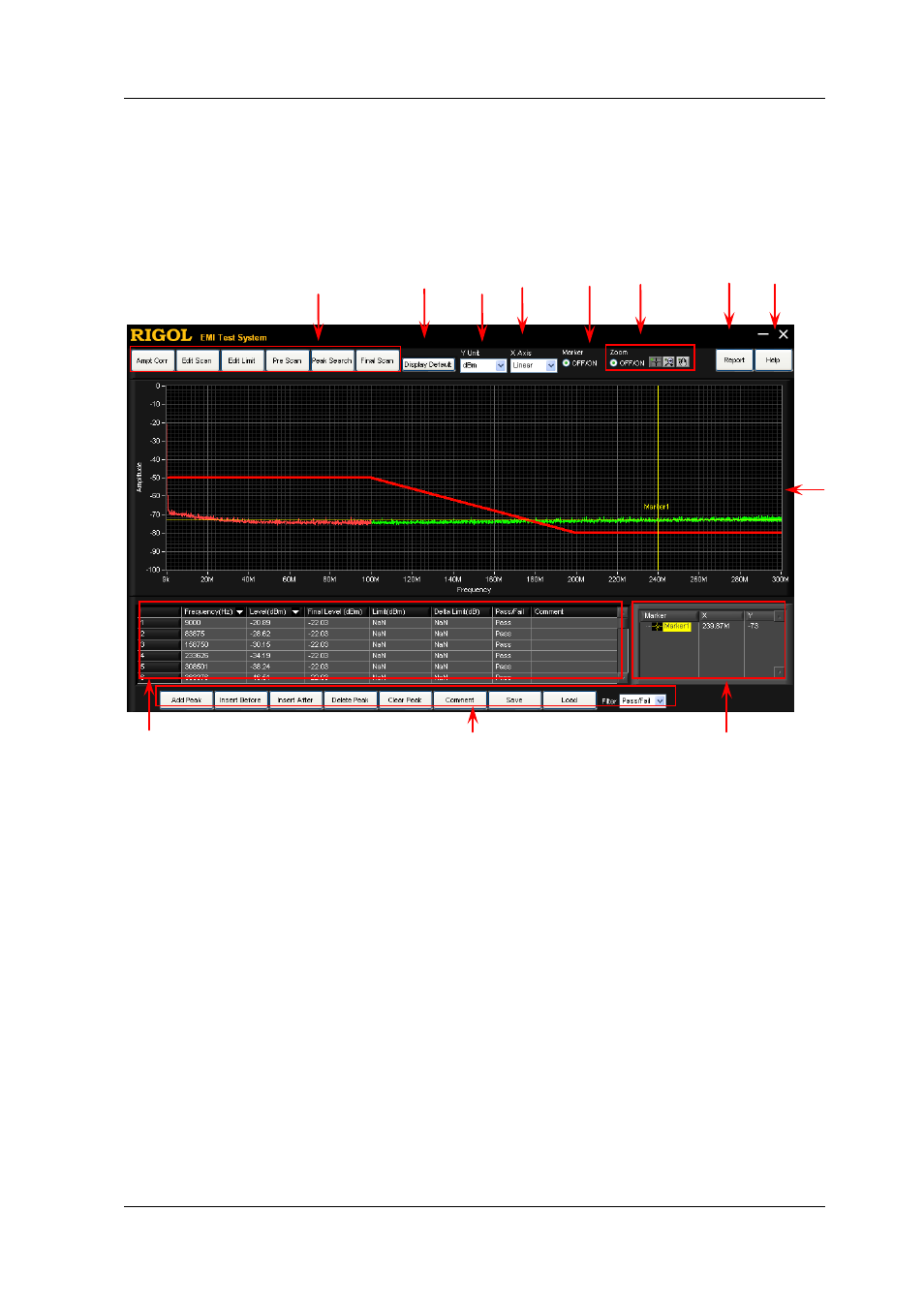
The interface layout of EMI Test System is as shown in the figure below.
Figure 3-1 EMI Test System Interface Layout
1. Software function keys
EMI Test System provides amplitude correction data editing (Ampt Corr),
scan parameter setting (Edit Scan), limit line editing (Edit Limit), pre-scan
(Pre Scan), peak search (Peak Search) and final scan (Final Scan)
functions.
2. Display the default scan range
When the maximum or minimum value of the frequency axis in the spectrum
window is modified manually, the spectrum window displays the spectrum
within the current frequency range. At this point, you can restore the
frequency axis range of the spectrum window to the default scan range by
clicking Display Default.
8
1
2
3
4
5
6
7
9
11
10
12