RISCO Group axesplus® User Manual
Page 46
User Manual for Hardware Installation
Uncontrolled when printed
© RISCO Group
45
8.3
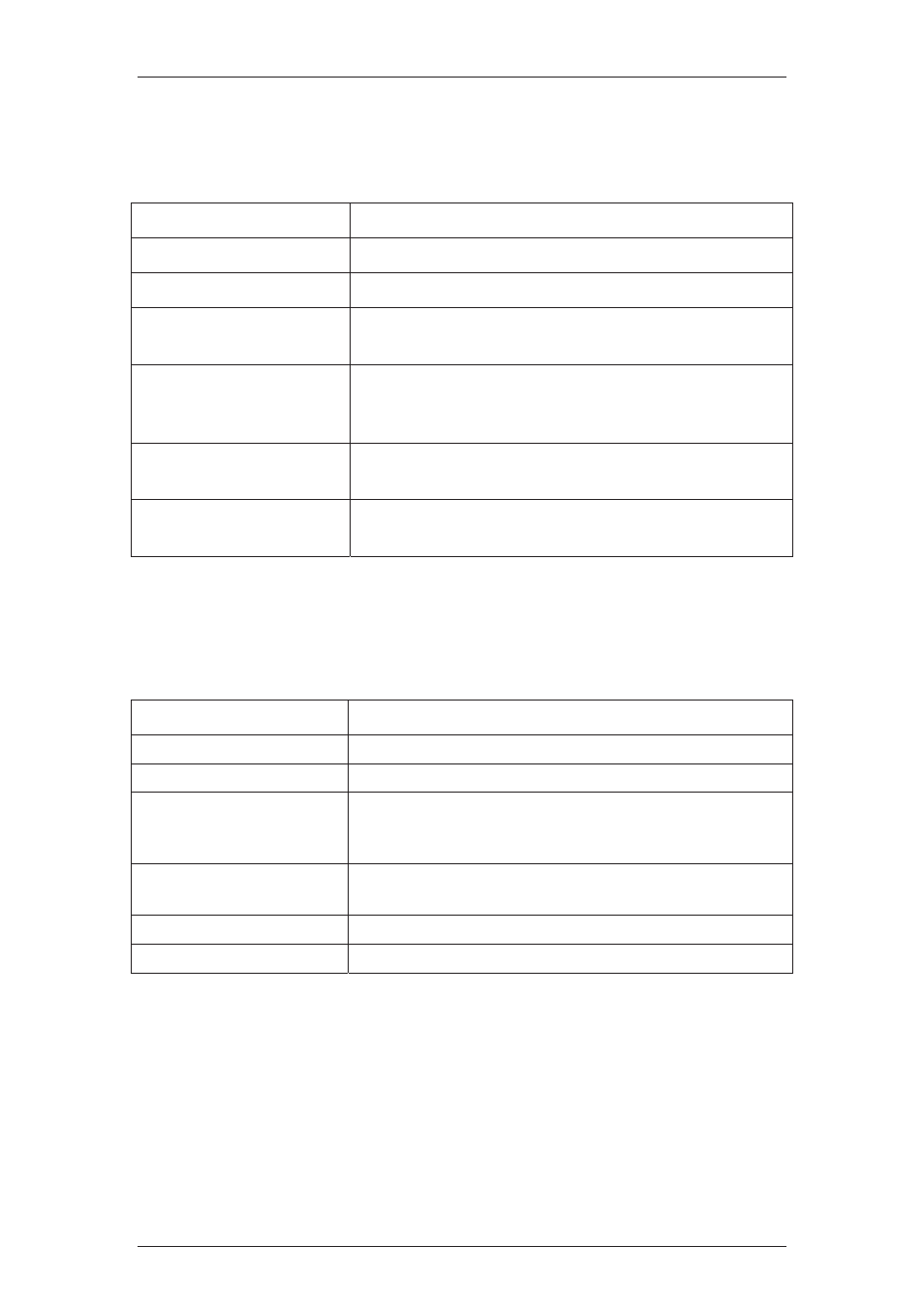
LED Indications for ACIB
ACIB LED indications are described in the following table.
Table 4: LED Indications
LED Type
Description
3V3 LED
It indicates Power of the ACIB.
Communication failure
This LED glows if ACIB communication fails with ACCB
Relay ZONE (8 in number)
Each door has relay Zone and each relay has monitoring red LED
which will get activated when relay is latched.
Door Input Signals (8 in
number)
Each door has 4 input signals sampling by the CPU with respect to
4 ground contacts (0v). Each input monitored by red LED which
will be active if the input is low.
Power System 12V
The Power system LED which is just beside the Power system
connector will be ON if the power is supplied to the ACIB.
Power Relay 12V
The Power relay LED which is just beside the Power relay
connector, will be ON if the Power is supplied to the ACIB
8.4
Seven Segment Display of ACIB
Seven segment displays is available on the ACIB for specifying two characters. Following table
shows the various character codes and their description:
Table 5: Character Codes for 7 segment display
Character Code
Description
00
No Application firmware is present.
B1 In
bootloader
dC
Default configuration (when ACIB has not connected with ACCB at
the beginning)
1d Direct
programming
mode
AC
Acquired Configuration(acquired from ACCB)
dF Downloading
Firmware