RISCO Group axesplus® User Manual
Page 36
User Manual for Hardware Installation
Uncontrolled when printed
© RISCO Group
35
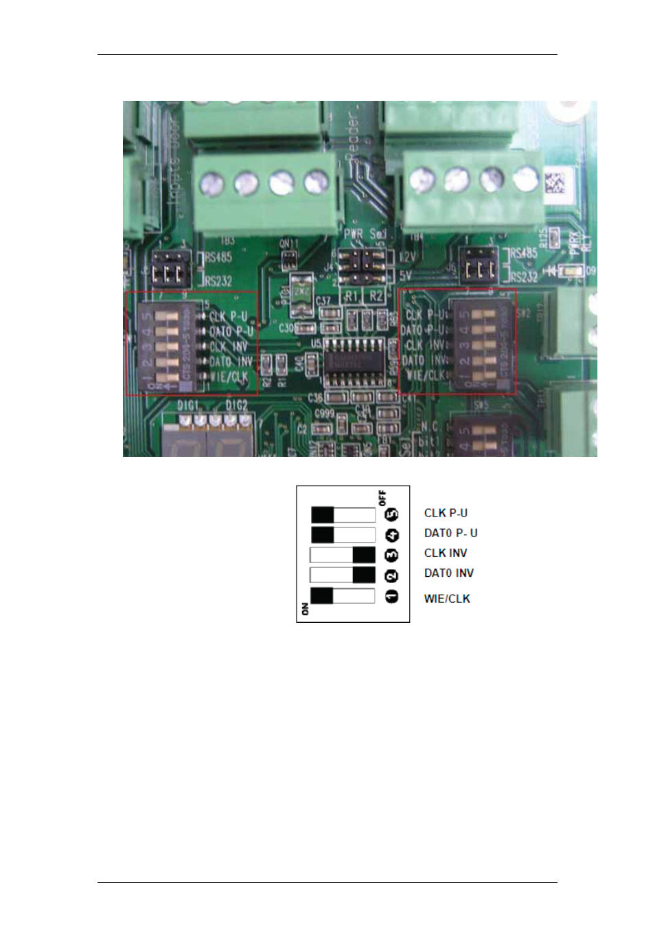
Figure 24: DIP Switch
Setting description:
1. WIE/CLK: “ON”=WIE, “OFF”=CLK.
2. DAT0 INV: “ON”=INV, “OFF”=NOT INV.
3. CLK INV: “ON”=INV, “OFF”=NOT INV.
4. DAT0 P-U: “ON”=Enable Pull-UP resistor,
“OFF”=Disable Pull-UP resistor.
5. CLK P-U: “ON”=Enable Pull-UP resistor,
“OFF”=Disable Pull-UP resistor.
Here,
WIE = Wiegand Interface, CLK = Clock/ Data interface, INV = Inverted