RISCO Group axesplus® User Manual
Page 29
User Manual for Hardware Installation
Uncontrolled when printed
© RISCO Group
28
6.5
Relay
You have a Relay Zone and Relay Feed as seen from the points 15a, 15b and 14a, 14b respectively
(Refer
Figure 10: ACIB BOARD
) on the ACIB.
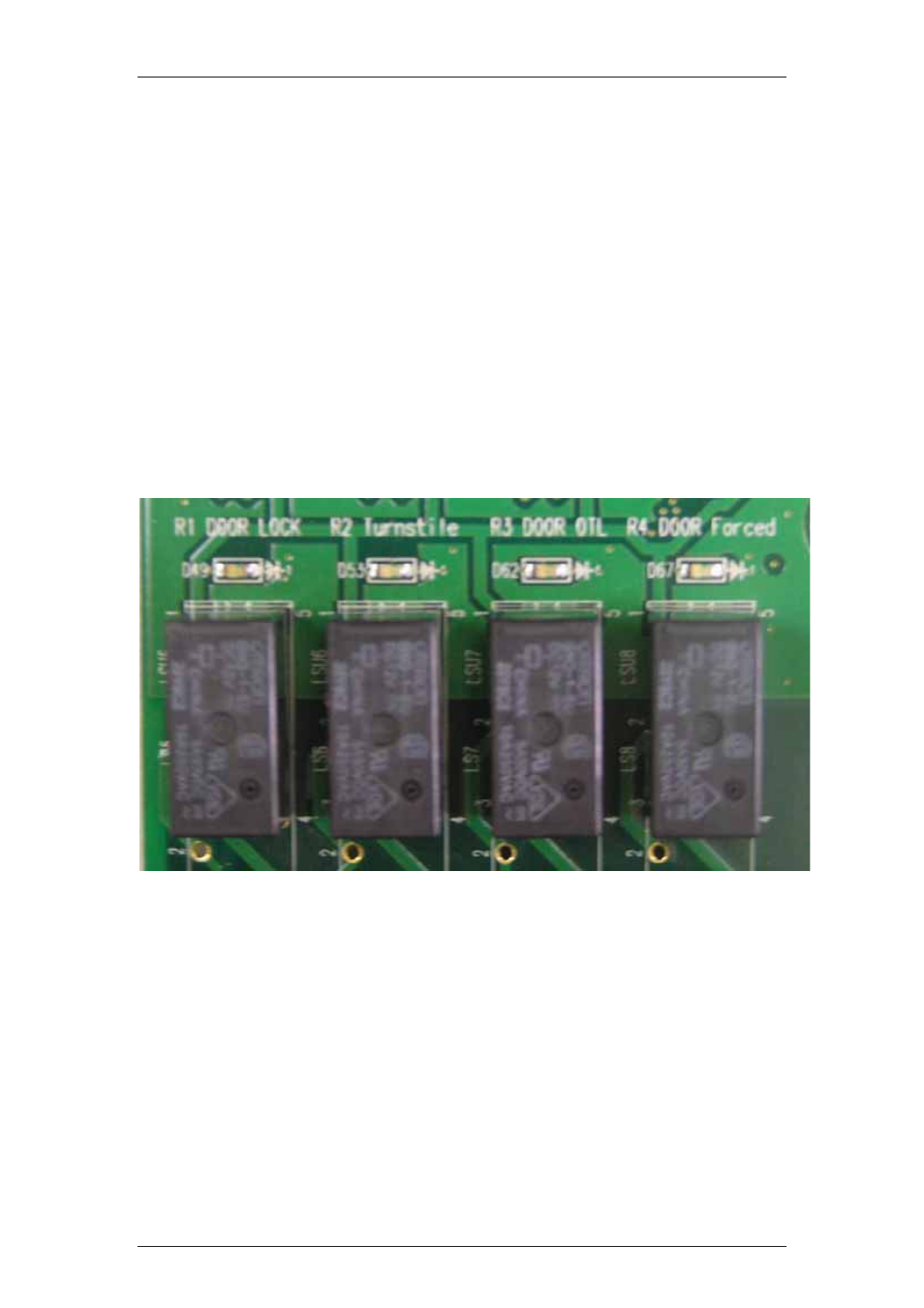
Relay Zone
Each door has relay zone which contains interfacing terminal, 4 relays and feeding option for relay
1.
Following are the relays used with their specific purpose:
• DOOR Forced – Forced Door Relay
• DOOR OTL – Door Open Too Long
• Turnstile (lock 2)
• DOOR Lock (lock 1)
Figure 15: Relay Zone
The interfacing terminal allows the user to build an external circuitry using 12v, ground and relay
contacts – controlled by the CPU. Each relay has monitoring red LED active when the relay is
latched.
For more details, refer: 15a, 15b (Figure 10: ACIB BOARD )
Relay Feed
Door 1, 2 have special features for relay 1 (in each door), the user can choose to feed the relay N.C or
N.O contact with 12V by short the right pins on J7 and J11 (referring to doors 1,2 respectively).
When removing all the shorts, the relay acts like a normal relay without any feed.