Precision Digital PD6310 User Manual
Page 24
Model PD6210 & PD6310 Batch Controllers
Instruction Manual
24
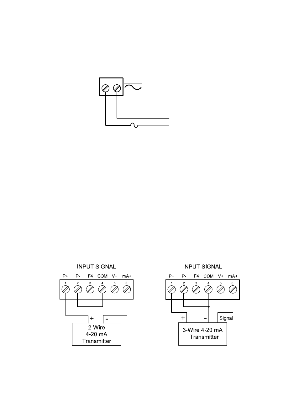
Power Connections
Power connections are made to a two-terminal connector labeled POWER
on Figure 6. The controller will operate regardless of DC polarity
connection. The + and - symbols are only a suggested wiring convention.
AC or DC
POWER
Required External Fuse:
5 A max, 250 V Slow Blow
POWER
+ -
Figure 8: Power Connections
PD6210 Signal Connections
Signal connections are made to a six-terminal connector labeled
SIGNAL on Figure 6. The COM (common) terminal is the return for the
4-20 mA and the
±10 V input signals.
Current and Voltage Connections
The following figures show examples of current and voltage connections.
There are no switches or jumpers to set up for current and voltage inputs.
Setup and programming is performed through the front panel buttons.
Figure 9: Transmitters Powered by Internal Supply