Important – MCZ PowerBox COMPACT User Manual
Page 11
Chapter 2
INSTALLATION AND USE MANUAL
page
11
Theoretical notions for installation
Technical service - Rights reserved MCZ S.p.A. - Reproduction prohibited
•
be protected by a grille, metal mesh or suitable guard, as long as
this does not reduce the area below the minimum.
•
be positioned in such a way as to be impossible to obstruct
It is not compulsory to connect the air intake directly
with the stove (so that it draws air directly from
outside), but it is essential at all events to ensure an
airflow of 50 cubic metres per hour by the use of a
hole of the dimensions given.
See standard UNI 10683 REV.
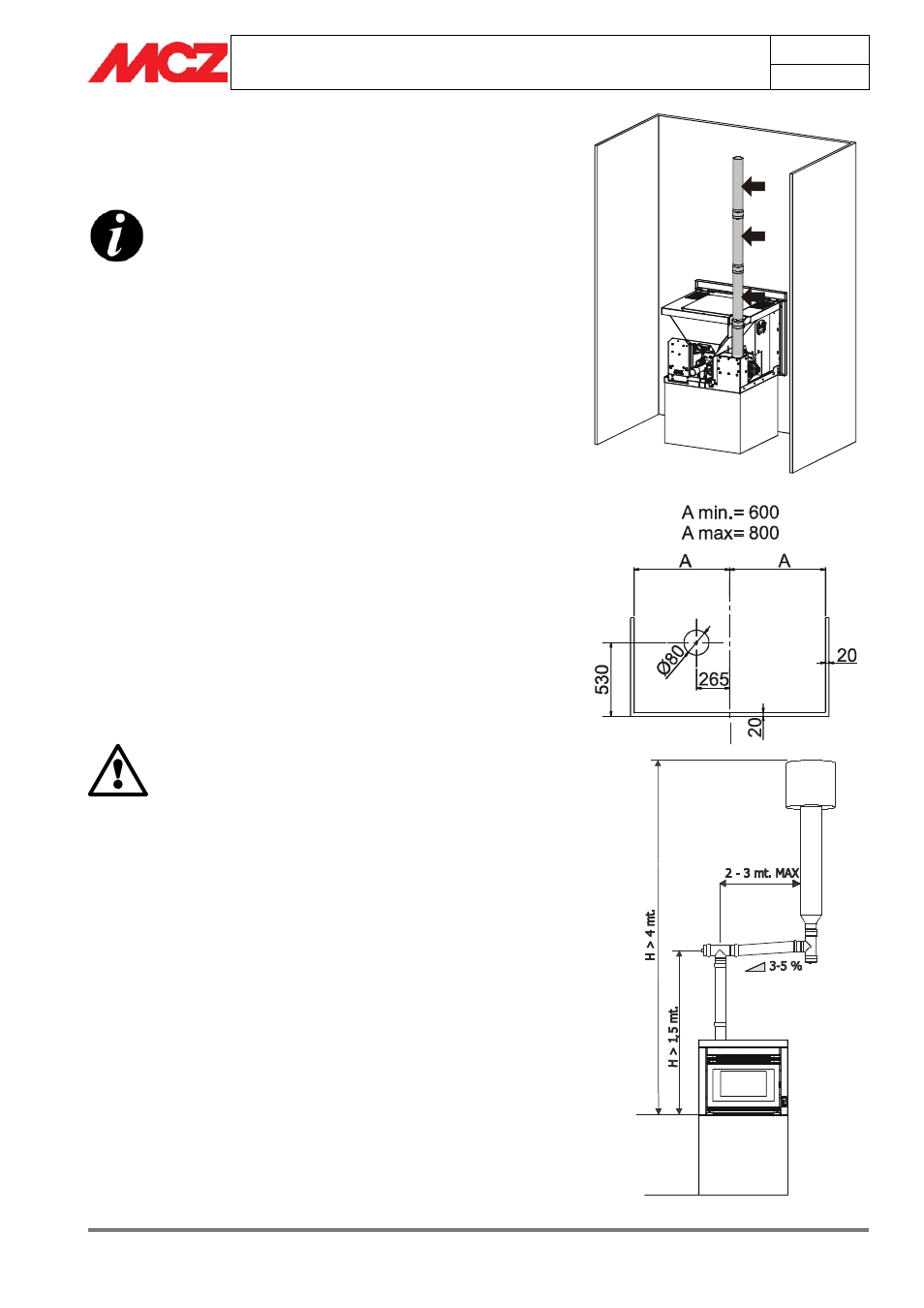
2.5. CONNECTION OF SMOKE DISCHARGE PIPE
When making the hole for the passage of the smoke discharge pipe, it
is necessary to take into account the possible presence of flammable
materials. If the hole will be going through a wall made of wood or any
other material which is sensitive to heat, the INSTALLER MUST first
of all use the special wall union (diam.13cm 13cm minimum) and
properly insulate the pipe of the stove that passes through it, using
adequate insulation materials (thickness 1.35cm with minimum thermal
conductivity of 0.07 W/m°K).
The same is true if the stove pipe must run through vertical or
horizontal stretches passing in proximity (min.20cm) to the heat-
sensitive wall
As an alternative we recommend the use of insulated pipe, which can
also be used on the outside to avoid condensation.
The combustion chamber works in low pressure. The smoke duct for
the discharge of fumes will also be under low pressure when connected
to an efficient flue pipe as directed.
IMPORTANT!
• All 90 degree changes of direction in the flue pipe
must be fitted with suitable tee connectors to
allow the possibility of inspection. (see
accessories for pellet stove)
• It is absolutely prohibited to fit a grille on the end
of the discharge pipe, because it could lead to
poor running of the stove.
• FOR CONNECTION TO THE FLUE PIPE, NOT MORE
THAN 2-3 METRES OF HORIZONTAL PIPE MUST
BE USED AND NOT MORE THAN THREE 90°
CURVES MUST BE USED
• IT IS ALSO ADVISABLE NOT TO EXCEED 6
METRES IN LENGTH WITH THE PIPE Ø 80 mm
• THE TUBE Ø 80 mm IS NEEDED ONLY TO
CONNECT THE FLUE PIPE AND CANNOT ITSELF
BE CONSIDERED AS A FLUE PIPE. The flue pipe
has the following characteristics described in
subsequent paragraphs
Example of installation of PowerSystem
Connection of smoke discharge pipe
Diagram