3 battery charging – Magnum Energy MS-G Series User Manual
Page 51
©
2015 Sensata Technologies
Page 43
Operation
3.3 Battery
Charging
The MS-G Series is equipped with a PFC (Power Factor Corrected) and PI (Proportional-Integral)
multi-stage battery charger. The PFC feature controls the amount of power used to charge the
batteries to obtain a power factor as close as possible to 1 (or unity). This causes the battery charger
to look like a resistor to the line (forces the charge current wave shape to mirror the voltage wave
shape). The PI feature allows the charger voltage and current to change independently. These two
features maximize the real power available from the AC power source (i.e., utility or generator),
which translates into less power wasted and increased charging capabilities.
When an AC source is connected to the AC input, the inverter begins monitoring for acceptable AC
voltage. Once the AC voltage is accepted, the AC transfer relay closes and Charge mode begins.
After Charge mode begins, the inverter’s battery voltage is monitored to determine the charging
stage. If the battery voltage is low (≤12.8 VDC/12-volt models or ≤25.6 VDC/24-volt models), the
charger begins bulk charging. If the DC voltage is high (>12.8 VDC/12-volt models or >25.6 VDC/
24-volt models), the charger will skip the Bulk and Absorb charge stages and go directly to Float
charging. However, if the incoming AC power is lost and returns within 2 minutes the charge mode
returns to the charge stage it was in prior to losing AC input—regardless of the battery voltage.
The multi-stage charger in the MS-G Series can use up to fi ve different charging stages to help
monitor and keep the batteries healthy. The fi ve stages include an automatic 4-stage charging
process (see Figure 3-5)—Bulk, Absorb, Float, and Full Charge—and a manual Equalization (EQ)
charge stage. The automatic 4-stage charge process provides complete recharging and monitoring
of the batteries without damage due to overcharging. The EQ stage (requires a remote control
display to enable) can be used to stir up stratifi ed electrolyte and to reverse any battery plate
sulfation that may have occurred—if recommended by your battery’s manufacturer.
While charging, the unit may go into charger back-off protection, which automatically reduces the
charge current to the batteries. This is caused by: 1) The internal temperature is too hot – the
charger automatically reduces the charge rate to maintain temperature; or 2) The AC input voltage
falls below 90 VAC – the charger will stop charging to help stabilize the incoming AC voltage.
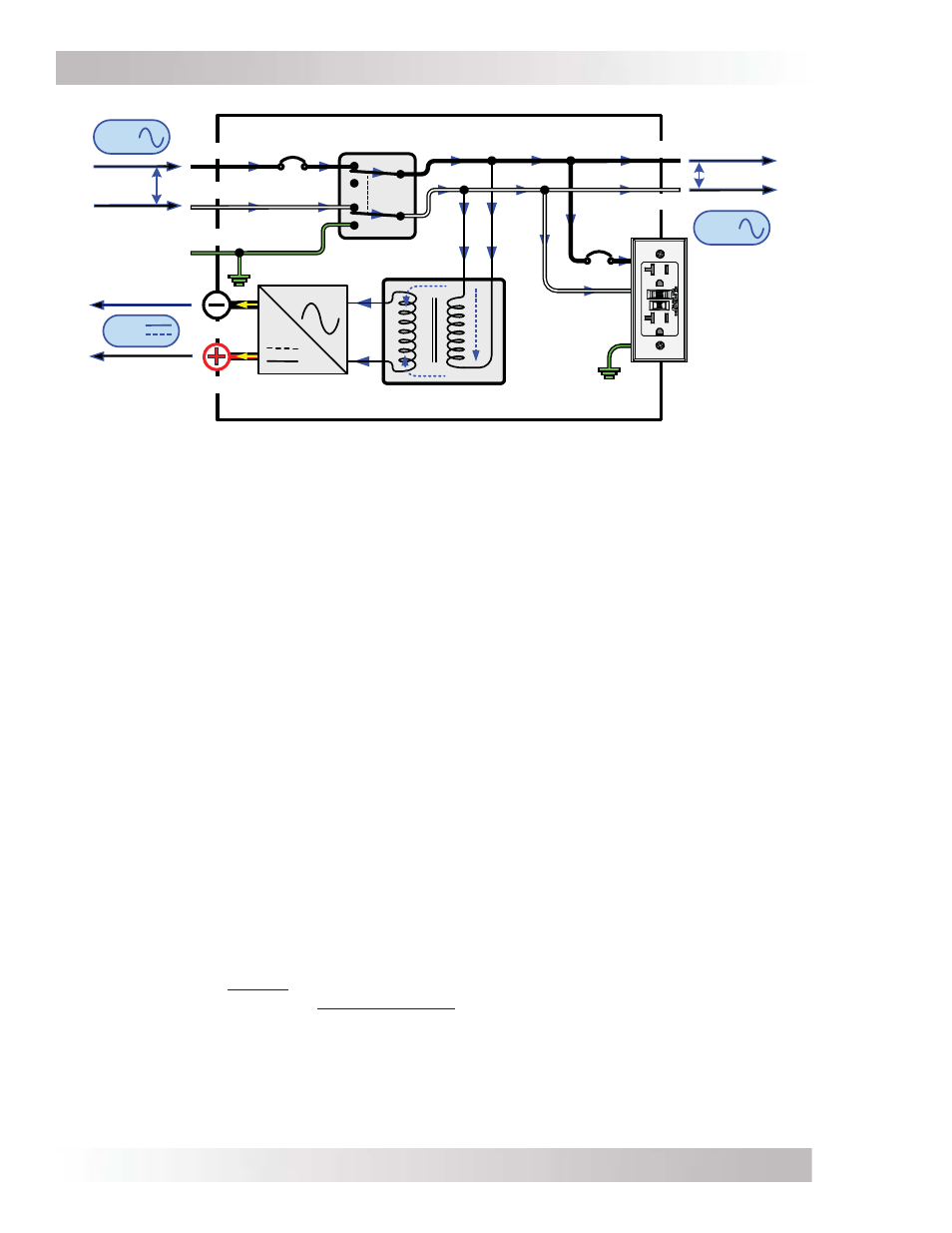
Figure 3-4, Power Flow – Standby Mode (MS2000-G model)
DC
OUT
120 VAC
AC NEU OUT
GFCI
120 VAC
OUTPUT
Neutral-Ground
Transfer Contact
AC Hot
Transfer Contact
AC HOT 1 OUT
AC HOT 1 IN
INPUT
(30A)
AC NEU IN
AC GROUND
GFCI
(20A)
Power Transformer
FET Bridge
AC
DC
DC POS
DC NEG
AC
OUT
120 VAC
AC
IN