Installation, Gfci – Magnum Energy MS-G Series User Manual
Page 34
Page 26
©
2015 Sensata Technologies
Installation
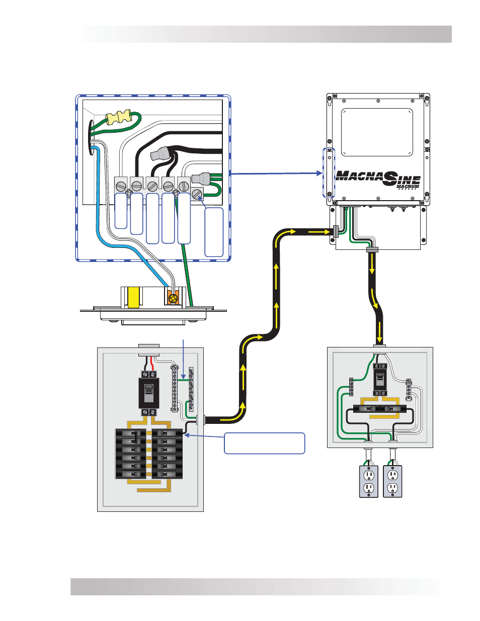
Figure 2-13, AC Wiring for Single In (50A) – Single Out Confi guration
Main Panel
(Utility/Generator Input)
SI/SO wiring (≤ 50A)
ON
OFF
ON
OF
F
ON
OF
F
ON
OF
F
ON
OF
F
ON
OF
F
ON
OF
F
ON
OF
F
ON
OF
F
ON
OF
F
ON
OF
F
ON
OF
F
ON
OF
F
60
NOTE: In mobile installations, the
neutral is typically not connected to
ground in main panel.
ON
OFF
AC Terminal Block
(AC input and output wiring)
MS-G Inverter
Sub-Panel and Outlets
(Inverter Loads)
120
VAC
Maximum 60-amp breaker
(single pole) required to
inverter AC input
See NOTE below
ON
OF
F
120
VAC
GFCI
AC
N
E
U
T
2
OU
T
AC
H
O
T
2
O
U
T
AC
H
O
T
2
I
N
(f
ro
m ma
in
p
an
e
l)
AC
H
O
T
1
I
N
(f
ro
m ma
in
p
an
e
l)
AC
N
E
U
T
I
N
(f
ro
m ma
in
p
an
e
l)
AC
G
R
O
U
N
D
S
(f
ro
m ma
in
p
an
e
l,
to
o
u
tl
e
t)
ON
OF
F