2 mounting the inverter, Installation 2.2 mounting the inverter, Figure 2-3, approved mounting positions – Magnum Energy MS-G Series User Manual
Page 18
Page 10
©
2015 Sensata Technologies
Installation
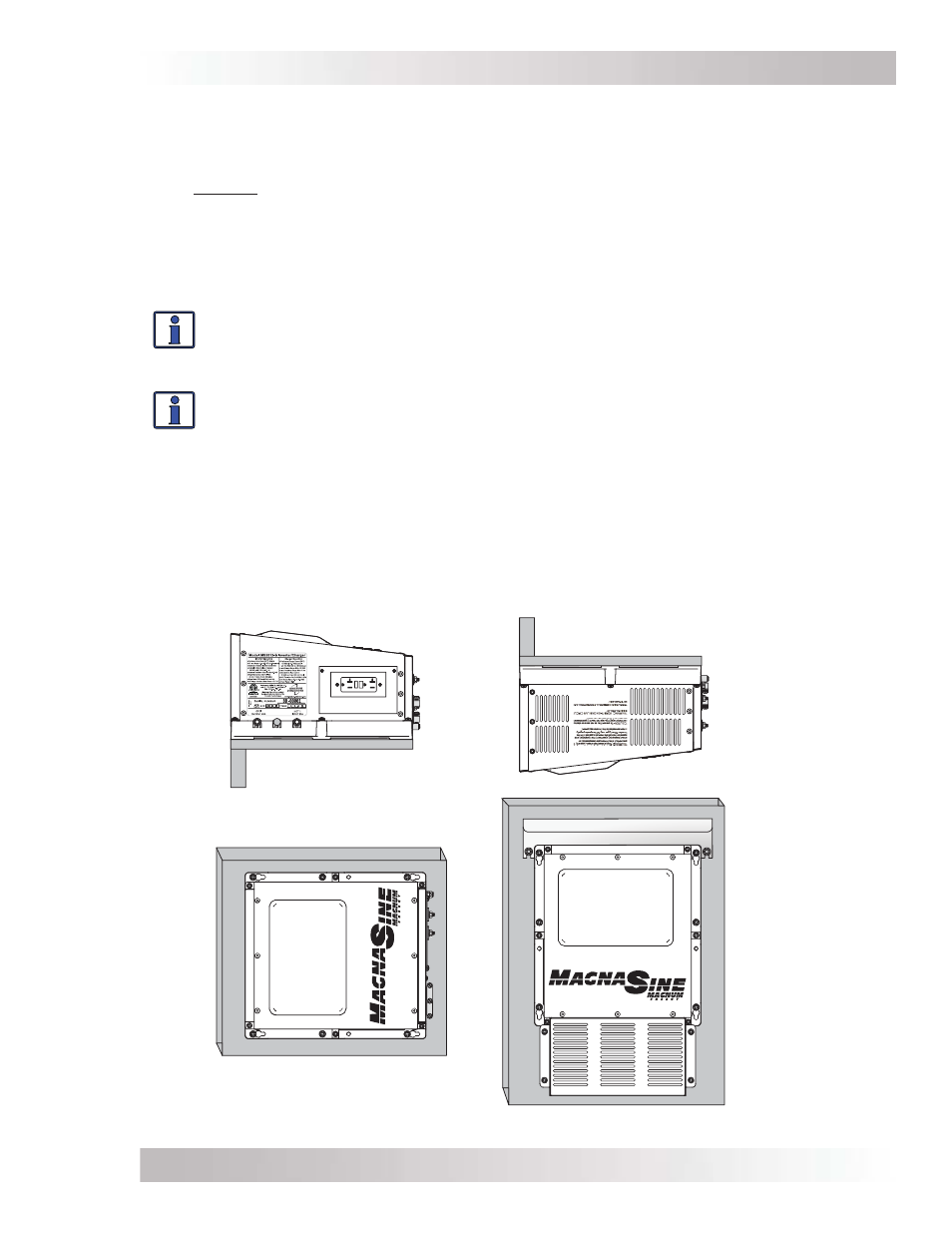
2.2 Mounting the Inverter
The inverter base can reach a temperature up to 90°C (194°F) and should be mounted on a
noncombustible surface*. This surface and the mounting hardware must also be capable of
supporting at least twice the weight of the inverter. To meet regulatory requirements, the MS-G
Series must be mounted in one of the following positions as shown in Figure 2-3:
• above or under a horizontal surface (shelf or table),
• on a vertical surface (wall) with the DC terminals to the right,
• on a vertical surface (wall) with the DC terminals toward the bottom, the MP-HOOD (inverter
hood) installed on the top, and either the ME-CB or MPX-CB (Conduit box), or the MMP series
(single inverter enclosure) installed on the inverter’s bottom.
Info: The ME-CB, MPX-CB, and MMP Series enclosures prevent material from falling
out the bottom in the event of an internal fi re, and also allow suffi cient ventilation to
prevent the inverter from overheating under normal operating conditions. The MP-
HOOD inverter hood prevents items from falling inside causing damage to the inverter.
Info: Sensata provides a backplate for mounting the inverter. These backplates also
provide the ability to mount the MMP Series enclosure (PN: BP-MMP).
After determining the mounting position, refer to the physical dimensions as shown in Figures
2-4 or 2-5, or use the base of the inverter as a template to mark your mounting screw locations.
After marking the mounting screw locations, mount the unit with appropriate mounting hardware.
* Noncombustible surface – A surface made of material that will not ignite, burn, support combustion, or
release fl ammable vapors when subjected to fi re or heat as per the ASTM E136 standard. For the most part,
these are materials that are largely comprised of inorganic materials such as stone, steel, iron, brick, tile,
concrete, slate, and glass. Avoid common building materials such as gypsum board as well as any paint, wall
coverings, and all types of wood.
Figure 2-3, Approved Mounting Positions
30
30
TE
S
T
RE
S
E
T
20
S
HELF
OR
T
ABLE
M
OUNTED
(
RIGHT
SIDE
UP
)
S
HELF
OR
T
ABLE
M
OUNTED
(
UP
SIDE
DOWN
)
W
ALL
M
OUNTED
(DC
TERMINALS
TO
THE
RIGHT
)
W
ALL
M
OUNTED
(DC
TERMINALS
FACING
DOWN
*)
*W
HEN
THE
INVERTER
IS
MOUNTED
ON
THE
WALL
IN
THIS
POSITION
,
THE
INVERTER
HOOD
(MP-HOOD)
MUST
BE
MOUNTED
OVER
THE
EXHAUST
VENTS
(
TOP
);
AND
EITHER
A
CONDUIT
BOX
(ME-CB
OR
MPX-CB)
OR
MMP
S
ERIES
ENCLOSURE
MUST
BE
ATTACHED
TO
THE
INVERTER
’
S
DC
END
(
BOTTOM
).