6 disabling the neutral-to-ground connection, 7 connecting a large dc ground wire – Magnum Energy MS-G Series User Manual
Page 46
Page 38
©
2015 Sensata Technologies
Installation
2.6.6
Disabling the Neutral-to-Ground Connection
All MS-G Series inverter/chargers have the automatic neutral-to-ground switching feature. In some
installations/jurisdictions, this feature must be disabled by disconnecting the neutral-to-ground
connection¹. If you are not sure whether you must disable this feature, check your local code
requirements. The following steps will guide you in disabling the neutral-to-ground switching feature.
Note¹ – The neutral-to-ground switching feature cannot be disabled in MS2000-G models.
Info: The ground connection from the inverter’s AC and DC ground terminals should
still be connected to the system ground, even if ground switching has been disabled.
WARNING: Fire and Shock Hazard—disconnect all AC and DC sources before working in
the AC wiring compartment.
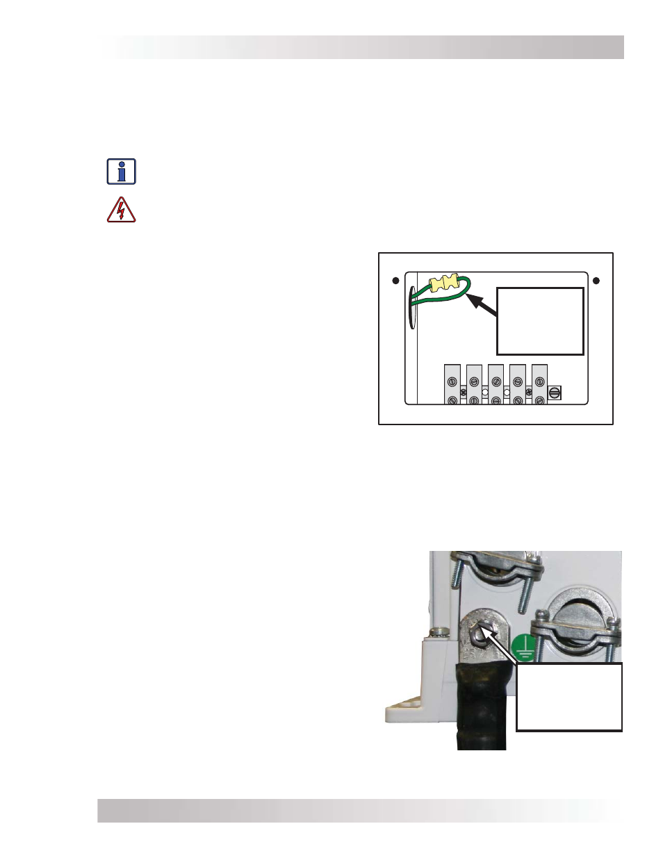
Figure 2-23, Disconnecting the
Neutral-to-Ground Connection
Neutral-to-
Ground
Connection
(green wire)
2.6.7
Connecting a Large DC Ground Wire
Some marine installations require the DC ground wire to be the same size or one size smaller
than the negative cable. Use the following steps to allow a larger ground wire to be connected.
Figure 2-24, Connecting a Large DC
Ground Wire
DC Ground
terminal bolt/nut,
reversed and
tightened.
1. Locate and remove the AC access cover plate
(Figure 1-3, Item 15) on the MS-G inverter.
2. Locate the DC ground terminal (Figure 1-2,
Item 7).
3. Within the AC wiring area, locate the hex nut
on the back side of the DC ground termi-
nal. After locating the hex nut, use a 7/16”
wrench/nut driver to remove the hex nut,
bolt, lock washer, and DC ground terminal—
remove them from the chassis.
4. Reverse the removed bolt and place it back
in the chassis hole to attach a correctly sized
ground cable with a ring terminal to the MS-G
Series chassis as shown in Figure 2-24.
Note: Ring terminal must have a hole size ≥1/4”.
5. Place the washer and nut on the bolt over the
ground cable and securely tightened the nut
[from 4 to 5 lbf-in (5.4 to 6.8 N-m)].
1. Locate and remove the AC access cover plate
(Figure 1-3, Item 15) on the side of the MS-G
Series inverter.
2. Inside the AC wiring compartment, locate
the green wire with the insulated connector;
see Figure 2-23. This insulated connector
connects the neutral and ground inside the
inverter while inverting.
3. Pull the two ends of the insulated connector
apart to separate the green wire; this will
prevent the neutral and ground from con-
necting inside this inverter.
4. Move the two disconnected ends away from
each other and push back out of the way. You
must ensure that the two connector ends will
not have any contact with any other wires
within the AC compartment. You may want
to use electrical tape to insulate the ends and
secure them out of the way.