4 ac terminal block connections, Installation – Magnum Energy MS-G Series User Manual
Page 29
©
2015 Sensata Technologies
Page 21
Installation
WARNING: Risk of electric shock. Use only ground-fault circuit interrupters [receptacle(s)
or circuit breaker(s)] that are compatible with your MS-G inverter. Some types may fail
to operate properly when connected to this inverter equipment.
2.5.4
AC Terminal Block Connections
The MS2012-G, MS2812-G, and MS4024-G models have a fi ve-pole AC terminal block and one
AC ground terminal to connect the inverter’s AC input and output wiring. This terminal block (see
Figure 2-10) allows a service/distribution panel (main panel) to be wired to the inverter’s input,
and also allows a dedicated panel (sub-panel) between the inverter’s output wiring and the AC
loads. To access and view the AC terminal block and ground terminal, remove the two Phillips
screws holding the AC wiring access cover plate (see Figure 1-3, Item 15).
Each connection on the AC terminal block is rated to accept one #14 to #6 AWG (2.1 to 13.3 mm
2
)
CU stranded wire, or two #12 AWG (3.3 mm
2
) CU stranded wires. Each connection uses a M3.5
slotted head screw, and the maximum tightening torque is 16 lbf-in (1.8 N-m).
Info: One of the AC wiring confi gurations [SI/SO (50A), Figure 2-13] uses a #6 AWG
(13.3 mm
2
) CU wire to carry 60 amps, and splits to two wires to allow 30 amps for each
leg (i.e., AC HOT 1 IN and AC HOT 2 IN). IDEAL Industries Inc. (www.idealindustries.
com) manufactures a crimp connector (PN: 412) and a separate insulator (PN: 417)
that allow up to two #8 AWG (8.4 mm
2
) wires, with one #6 AWG (13 mm
2
) wire to be
connected together.
Info: To comply with ABYC requirements for marine installations, the AC terminal has
a stainless steel wire protector to prevent wire damage from the set-screw.
Info: The inverter’s NEUT IN and NEUT OUT terminals are electrically isolated from each
other while inverting. This is related to the neutral-ground bonding requirement and
helps prevent ground-loops (see Section 2.6.5 for more information). If the installation
requires the input and output neutrals to be connected together, the inverter’s neutral-
to-ground connection must be disconnected (see Section 2.6.6).
The AC ground terminal can accept one #14 to #6 AWG (2.1 to 13 mm
2
) CU stranded wire. It uses
a slotted head screw and has a recommended maximum tightening torque of 45 lbf-in (5.1 N-m).
For multiple ground wires, use a pressure or mechanical connector to attach the single wire from
the AC ground terminal to the input and output ground connections.
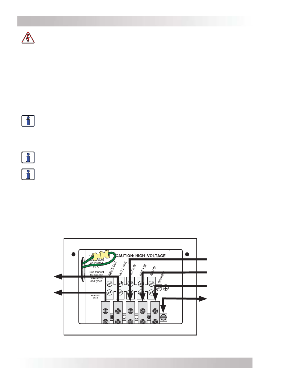
Figure 2-10, AC Terminal Block (MS2012-G/MS2812-G/MS4024-G)
AC GROUND
(In & Out)
NEUT IN
HOT 1 IN
HOT 2 IN
HOT 2 OUT
NEUT 2 OUT