8 ac wiring configuration (ms2000-g models) – Magnum Energy MS-G Series User Manual
Page 37
©
2015 Sensata Technologies
Page 29
Installation
2.5.8
AC Wiring Confi guration (MS2000-G models)
The following table provides the different wiring confi gurations for installing and connecting the
AC conductors to and from MS2000-G model inverters (see Figures 2-15 and 2-16 for installation
diagrams showing these confi gurations).
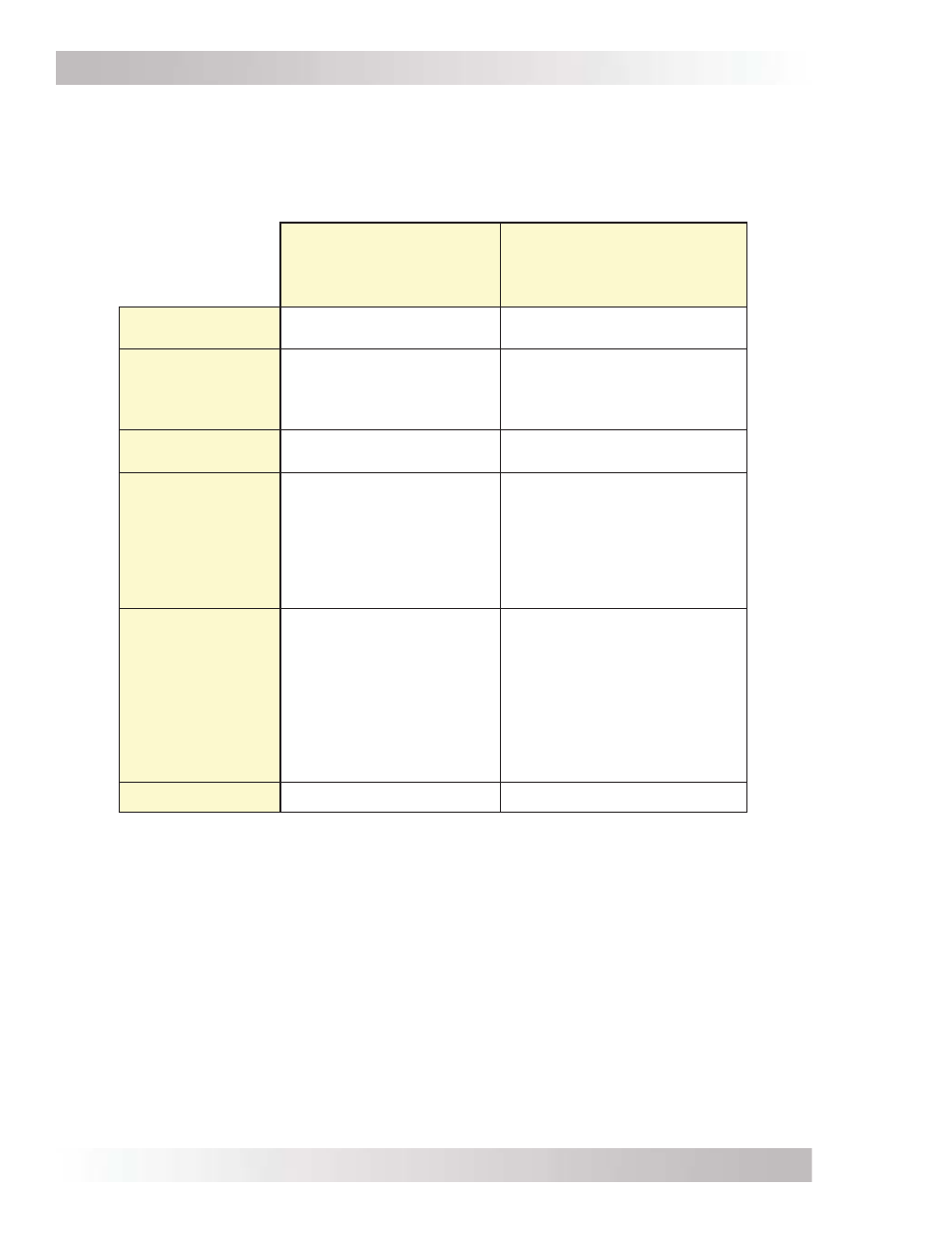
Table 2-4, AC Input/Output Wiring Confi gurations (MS2000-G models)
SI
Single In
SI/SO
Single In/Single Out
AC Input Source
1
120 VAC @ ≤30 amps
120 VAC @ ≤30 amps
Reason to Use
Have a 120 VAC source
that is ≤30 amps, and
using the GFCI outlet to
connect loads.
Have a 120 VAC source that
is ≤30 amps.
Requires a separate
inverter sub-panel.
Appropriate
Models
MS2000-G
MS2000-G
Maximum
Input Breaker
Required
-
Minimum Wire
Size
30A
(single pole)
-
#10 AWG
(In)
30A
(single pole)
-
#10 AWG
(In & Out)
Maximum
Inverter Pass-
thru capacity
-
Output
Confi gurations
2400W
-
20A @ 120 VAC
(GFCI outlet)
3600W
-
30A @ 120 VAC = 3600W
(HOT 1 OUT)
or
20A @ 120 VAC = 2400W
(GFCI outlet)
Wiring Diagram
Figure 2-15
Figure 2-16
Note
1
– AC Source is from either the utility/grid power (i.e., shorepower) or an AC generator.