Magnum Energy MS-G Series User Manual
Page 31
©
2015 Sensata Technologies
Page 23
Installation
2.5.6
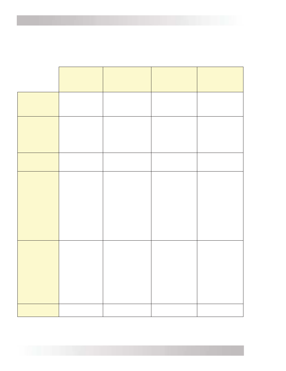
AC Wiring Confi gurations (MS2012-G, MS2812-G, MS4024-G)
The following table provides the different wiring confi gurations for installing and connecting the AC
conductors to and from the inverter (refer to Figures 2-11 to 2-14 for installation drawings showing
these confi gurations). Refer to Table 2-4 (and Figures 2-15 & 2-16) for the MS2000-G model.
Table 2-3, AC Input/Output Wiring Confi gurations
SI
Single In
SI/SO
Single In/
Single Out
(≤ 30A output)
SI/SO
Single In/
Single Out
(≤ 50A output)
DI/SO
Dual In/
Single Out
AC Input
Source
1
120 VAC @ ≤30
amps
120 VAC @ ≤30
amps
120 VAC @ >30
amps
(60 amps max.)
120/240 VAC
(or 2 separate
legs of 120 VAC)
2
@ ≤30 amps/leg
Reason to Use
Have an 120
VAC source that
is ≤30 amps,
and using the
GFCI outlet to
connect loads.
Have an 120 VAC
source that is ≤30
amps.
Requires a
separate inverter
sub-panel.
Have an 120 VAC
source that is
>30 amps.
Requires a
separate inverter
sub-panel.
Want dedicated
pass-thru while
AC source is on.
Requires a
separate inverter
sub-panel.
Appropriate
Models
MS2012-G
MS2812-G
MS4024-G
MS2012-G
MS2812-G
MS4024-G
MS2012-G
MS2812-G
MS4024-G
MS2012-G
MS2812-G
MS4024-G
Maximum
Input Breaker
Required
-
Minimum
Wire Size
(AWG)
30A
(single pole)
-
#10 AWG
(In)
30A
(single pole)
-
#10 AWG In
(split into two #10
AWG for HOT 1 &
HOT 2 IN)
#10 AWG Out
(HOT 2 OUT)
60A
(single pole)
-
#6 AWG In
(split into two
#10 AWG for
HOT 1 & HOT 2
IN)
#10 AWG Out
(HOT 2 OUT)
30A
(dual pole)
-
#10 AWG
(In & Out)
Maximum
Inverter Pass-
thru Capacity
-
Output
Confi gurations
2400W
-
20A @ 120 VAC
3600W
-
30A @ 120 VAC =
3600W
(HOT 2 OUT)
or
20A @ 120 VAC =
2400W
(GFCI outlet)
6000W
-
30A @ 120 VAC
(HOT 2 OUT)
and
20A @ 120 VAC
(GFCI outlet)
6000W
-
30A @ 120 VAC
(HOT 2 OUT)
and
20A @ 120 VAC
(GFCI outlet)
Wiring
Diagram
Figure 2-11
Figure 2-12
Figure 2-13
Figure 2-14
Note
1
– AC Source is from either the utility/grid power (i.e., shorepower) or an AC generator.
Note
2
– If two legs of 30A @ 120 VAC are used, they must be from the same source (i.e., have a common
neutral). For example, 2 legs from a 3-phase source can be used.