6 grounding inverters, Installation 2.6 grounding inverters – Magnum Energy MS-G Series User Manual
Page 40
Page 32
©
2015 Sensata Technologies
Installation
2.6 Grounding
Inverters
The inverter/charger should always be connected to a permanent, grounded wiring system.
An inverter system that is properly grounded will limit the risk of electrical shock, reduce radio
frequency noise from the inverter, and minimize excessive surge voltages induced by lightning. This
is done by ensuring there is a well-defi ned, very low-resistance path from the electrical system to
the grounding system. This low-resistance path helps stabilize the electrical system voltage with
respect to ground and carries fault currents directly to ground if the electrical system malfunctions.
To understand how the conductors in the electrical circuit will be connected to the system ground,
the following terms should be understood:
• Grounded
Conductor
(GC): The wire/cable in the electrical system that normally carries
current (usually AC neutral and/or the DC negative), and is intentionally connected or “bonded”
to the ground system. This wire, or the ends of this wire, should be colored white or gray.
• Equipment Grounding Conductor (EGC): A wire/cable that does not normally carry current
and is used to connect the exposed metal parts of equipment—that might be accidentally
energized—to the grounding electrode system or to the grounded conductor. This wire, or the
ends of this wire, should be green or green with a yellow stripe; this wire can be bare copper.
• Grounding Electrode Conductor (GEC): The wire/cable that does not normally carry
current and connects the grounded conductor and/or the equipment grounding conductor to
the grounding electrode at the service equipment.
• Grounding
Electrode
(GE): A ground rod or conducting element that establishes an electrical
connection to the earth.
• System bonding jumper (SBJ): The connection between the grounded circuit conductor in
the electrical system and the equipment grounding conductor at a separately derived system.
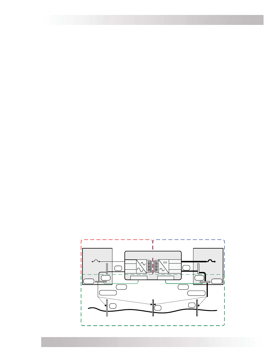
The MS-G Series inverter/charger uses both AC and DC power; however, the AC electrical system
is isolated from the DC electrical system by an internal transformer. Although this inverter/charger
has two electrical systems, each electrical system must be properly grounded and connected to
a common “earth” reference. Refer to Figure 2-17.
For proper grounding, each electrical system must connect all exposed metal parts of equipment
(via equipment grounding conductors – EGC) and one of the current-carrying conductors (grounded
conductor – GC) together at a common point (ground busbar – GBB), usually by a system bonding
jumper (SBJ) in an electrical service disconnect panel. The common point of each electrical system
is then connected (via grounding electrode conductor – GEC) to the common ground reference,
such as a ground rod (grounding electrode – GE). This connection to earth should only be made
at one point in each electrical system; otherwise, parallel paths will exist for the currents to fl ow.
These parallel current paths would represent a safety hazard and are not allowed in installations
wired per the NEC/CEC.
Figure 2-17, Grounding System for MS-G Series
AC
DC Service
Panel
AC Service
Panel
DC Electrical System
AC Electrical System
Neutral
Positive
Negative
DC
Grounding
System
Negative
SBJ
GC
GE
GEC-AC
EGC
AC Ground
DC Ground
SBJ
EGC
GC
Neutral
Hot
GEC-DC
GE
GE
GBB
GBB
Grounding Electrode
(AC and DC sides shared)
Grounding Electrode
(DC side dedicated)
Grounding Electrode
(AC side dedicated)
or
or
MS Series Inverter/Charger