3 description, 1 mode of operation, 2 description of the unit – KACO Powador 10.0 - 20.0 TL3 User Manual
Page 7: 3 description 3.1, Mode of operation, Description of the unit, 3description, 1 powador inverter as part of a pv system
EN
Description
Operating Instructions Powador 12.0 TL3-20.0 TL3
Page 7
3
Description
3.1
Mode of Operation
The inverter converts the DC voltage generated by the PV modules into AC voltage and feeds it into the grid. The
feed-in process begins when there is sufficient sunlight and a specific minimum voltage is present in the inverter.
If, as it gets dark, the voltage drops below the minimum voltage value, the feed-in operation ends and the inverter
switches off.
3.2
Description of the unit
3.2.1 Powador inverter as part of a PV system
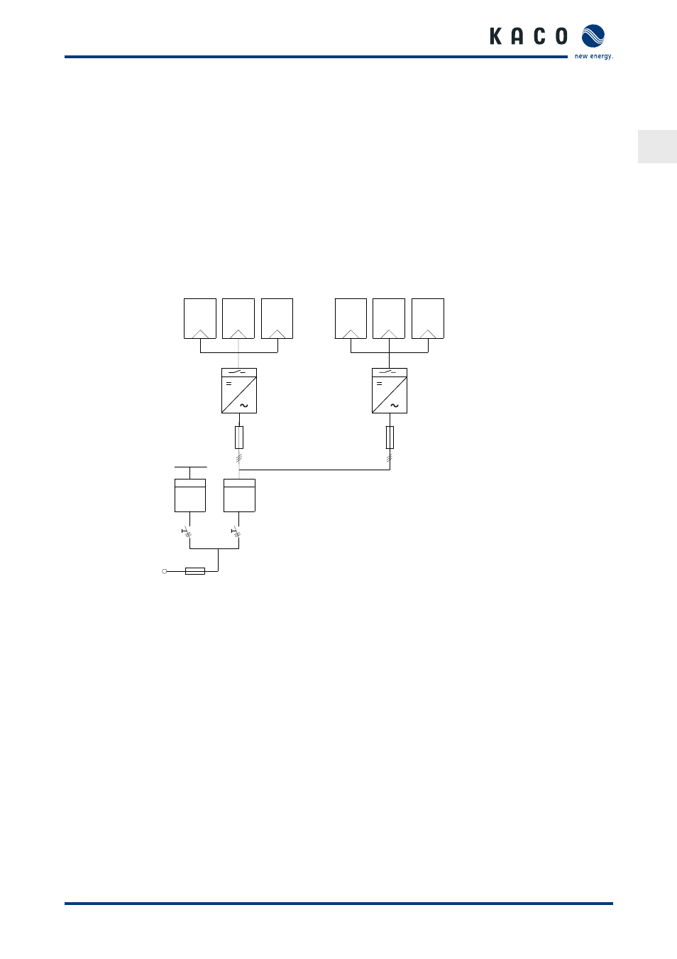
3.2.1.1 System layout
KWh
KWh
PV generator
PV generator
Powador with DC isolator
switch
Powador with DC isolator switch
Line protection
Line protection
Load
Feed-in meter
Reference
counter
Main switch
Grid connection
point
Selective main switch
Figure 1: Circuit diagram of a system with two inverters
3.2.1.2 Summary of the components
PV generator
The PV generator, i.e. the PV modules, converts the radiant energy of sunlight into electrical energy.
DC terminal point
Options for parallel connections of several generator strings:
•
To a DC terminal point between the DC generator and inverter.
•
Directly to the inverter (plug connectors for 4 (2 x 2) strings are provided on the inverter).
•
Directly to the PV generator with a positive and negative lead to the inverter.
DC isolator switch
Use the DC isolator switch to disconnect the inverter from all power sources on the PV generator side.
Grid fuses
gL safety fuses or automatic circuit breakers are suitable.