2 connecting the pv generator – KACO Powador 10.0 - 20.0 TL3 User Manual
Page 18
EN
EN
Installing the inverter
Page 18
Operating Instructions Powador 12.0 TL3-20.0 TL3
Authorised electrician
7.2.2 Connecting the PV generator
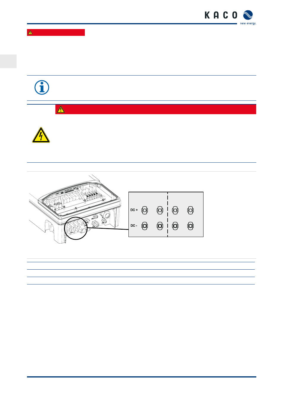
Connect the PV generator to the 4 DC positive and the 4 DC negative connection plugs on the underside of
the housing (see Figure 8 on page 18). Note the wiring examples given below. The inverter detects these typical
configurations automatically. In individual cases, you need to set the selected DC connection after installation in
the menu.
NOTE
Connected PV modules must be dimensioned for the DC system voltage in accordance with IEC 61730
Class A, but at least for the value of the AC grid voltage
DANGER
Risk of fatal injury due to contact voltages.
›
During installation: Electrically disconnect the DC positive and DC negative from the protective
earth (PE).
Removing the plug connection before disconnecting the inverter from the PC generator can result in
a hazard to health and damage to the inverter.
›
Disconnect the inverter from the PV generator using the integrated DC isolator switch.
›
Remove the plug connector.
1
A
B
2
3
4
Figure 8: Connections for DC positive and DC negative
Key
A
MPP tracker A
B
MPP tracker B
1.2 DC-Plus/DC-Minus-Connections to MPP tracker A
3.4 DC-Plus/DC-Minus-Connections to MPP tracker B