8 configuration and operation, 1 controls, Configuration and operation – KACO Powador 10.0 - 20.0 TL3 User Manual
Page 29: 8configuration and operation
EN
Configuration and Operation
Operating Instructions Powador 12.0 TL3-20.0 TL3
Page 29
Authorised electrician
8
Configuration and Operation
8.1
Controls
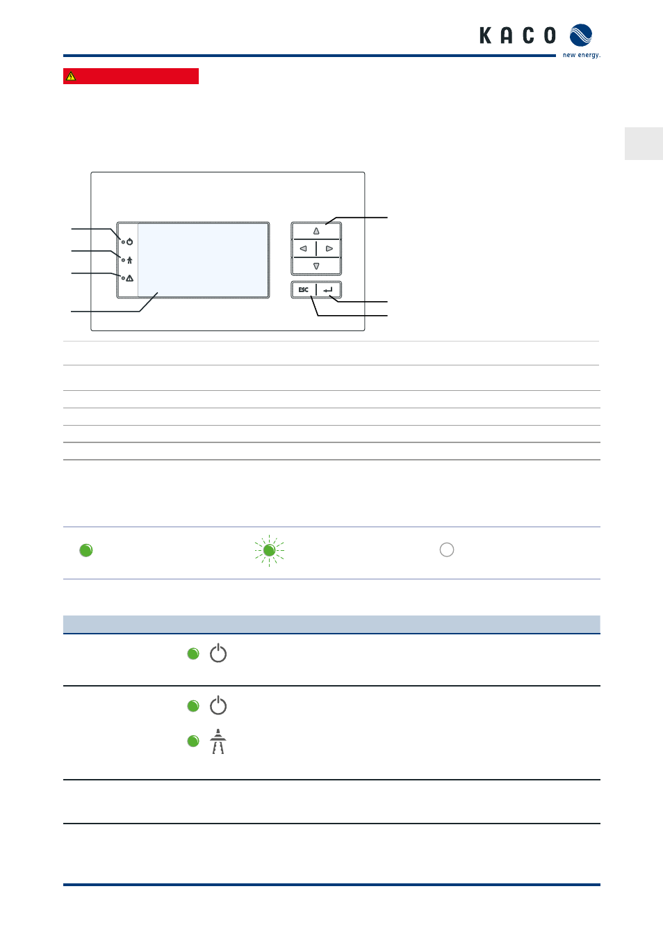
The inverter has a backlit LCD as well as three status LEDs. The inverter is operated using six buttons.
1
2
3
4
5
6
7
Figure 16: Control panel
Key
1
"Operating" LED
5
4-way button
2
“Grid-feed” LED
6
“OK” button
3
"Fault" LED
7
“ESC” key
4
LCD
8.1.1 LED indicators
The three LEDs on the front of the inverter show the different operating states.
The LEDs can display the following states:
LED illuminated
LED flashing
LED not illuminated
The LED indicators show the following operating status:
Operating status
LEDs
Display
Description
Start
The green "Operating" LED is illuminated
if an AC voltage is present,
(independently of the DC voltage).
Feed-in start
Power fed into the grid
or measured values
The green "Operating" LED is illuminated.
The green “Feed-in” LED is illuminated
after the country-specific waiting period*.
The inverter is ready to feed in, i.e. is on
the grid.
You can hear the grid relay switch on.
* The waiting period ensures that the generator voltage continuously remains above the power delivery limit
of 200 V.
For country-specific waiting periods see our web site at http://www.kaco-newenergy.de/.