KACO Powador 10.0 - 20.0 TL3 User Manual
Page 17
EN
Installing the inverter
Operating Instructions Powador 12.0 TL3-20.0 TL3
Page 17
Authorised electrician
7.2.1 Connecting the inverter to the power grid
The power connection wires are connected on the right of the connection area (see Figure 6 on page 16).
DANGER
Risk of fatal injury due to electric shock
Severe injury or death will result if the live connections are touched.
›
Switch off all power sources to the inverter before you insert the grid power cable into the unit.
›
Make sure that the device is isolated from the public power supply and the system power supply
before starting work.
Recommended conductor cross-sections and fuse protection of NYM cables for fixed wiring according to
VDE 0100 part 430
For cable lengths up to 20m, use the specified conductor cross-sections. Longer cable lengths require larger
conductor cross-sections.
Model
Conductor cross-
section
Fuse protection: gL safety fuses or comparable
automatic circuit breakers
Powador 12.0 TL3
6.0 mm²
25 A for 4.0 mm² conductor cross-section
Powador 14.0 TL3
6.0 mm²
25 A for 4.0 mm² conductor cross-section
Powador 18.0 TL3
6.0 mm²
32 A for 6.0 mm² conductor cross-section
Powador 20.0 TL3
6.0 mm²
32 A for 6.0 mm² conductor cross-section
Table 2:
Recommended conductor cross-sections and fuse protection of NYM cables
NOTE
When the line resistance is high (i.e. long grid-side cables), the voltage at the grid terminals of the
inverter will increase during feed-in to the grid. The inverter monitors this voltage. If it exceeds the
country-specific grid overvoltage limit value, the inverter switches off.
›
Ensure that the conductor cross-sections are sufficiently large or that the cable lengths are
sufficiently short.
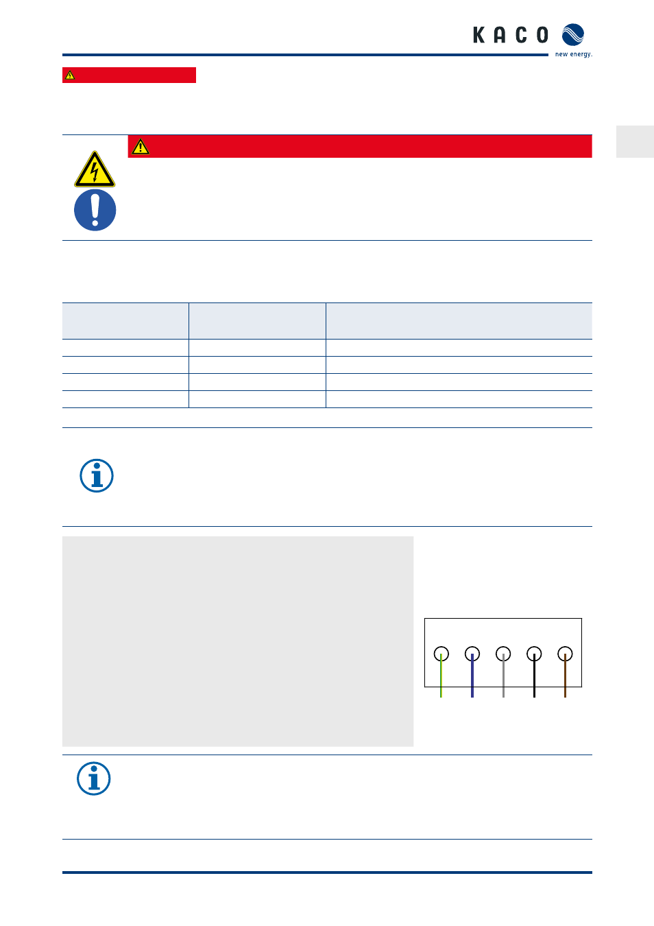
Making the grid connection
↻ Use cables with five wires (L1, L2, L3, N, PE).
1. Unscrew the cable fitting.
2. Remove the outer cladding of the AC cables.
3. Insert the AC leads through the cable fitting into the connection area.
4. Strip the insulation from the AC cables.
5. Open the locks for the PCB terminals.
6. Connect the cables in accordance with the label on the PCB terminals
7. Close the locks for the PCB terminals.
8. Check that all connected cables are securely fitted.
9. Tighten the cable fitting.
PE N
BU
L2
BK
L1
BN
GNYE
L3
GY
»
The inverter is now connected to the power grid.
Figure 7: AC connection terminals
NOTE
An AC-side disconnection unit must be provided in the final installation. This disconnection unit
must be installed so that it can be accessed at any time without obstruction.
If a residual current circuit breaker is necessary due to the installation specification, a type B residual
current circuit breaker must be used.