3 using the emergency stop input, Jconnecting the emergency stop switch, Jpower on sequence example – Yaskawa MP900 Teach Pendant User Manual
Page 18
1.2 System Configuration
1 -7
1.2.3 Using the Emergency Stop Input
An example of how to use the emergency stop switch on the Teach Pendant is described below.
J
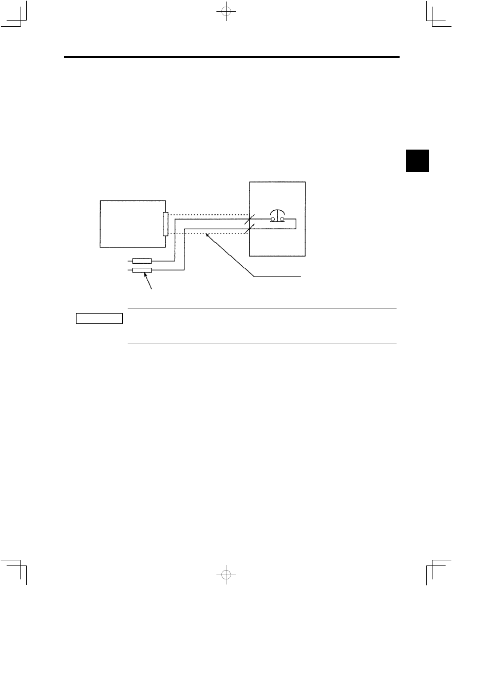
Connecting the Emergency Stop Switch
The emergency switch on the Teach Pendant cannot be detected inside either the Teach Pen-
dant or the MP9jj Machine Controller. When a standard Teach Pendant Cable is connected,
the switch connection wires can easily be pulled out, as shown in the following diagram.
JEPMC-MC350
PORT2
E-STOP1
E-STOP2
NP
JEPMC-W6030-05 (5 m)
Inside the Teach Pendant Cable
JEPMC-TB350
Emergency
stop switch
8
9
E-STOP1
E-STOP2
Cable disconnection i s m onitored by t he interface ladder for the MP9 jj Teach Pe ndant. T he monitoring, how-
ever, is affected by the scan time and other factors, and the circuit should be made to activate a hardware emergen-
cy stop.
J
Power ON Sequence Example
Construct the power ON sequence so that the main power supply to the Servo is turned OFF
when the Teach Pendant emergency switch is pressed.
The following diagram provides an example of that sequence. In this example, the main power
supply to the Servo will turn OFF when the Teach Pendant Cable is disconnected.
1
IMPORTANT