Yaskawa U1000 Industrial MATRIX Drive User Manual
Page 91
The “Safe Torque Off” state can only be achieved using the Safe Disable function. Removing the Run command stops the
drive and shuts the output off (baseblock), but does not create a “Safe Torque Off” status.
Note:
To avoid an uncontrolled stop during normal operation, make sure that the Safe Disable inputs are opened first when the motor has completely
stopped.
Returning to Normal Operation after Safe Disable
The Safe Disable function can only be deactivated when a Run command is not active.
If Safe Disable was activated during stop, turn on both Safe Disable inputs by deactivating “Safe Torque Off” to resume normal
operation.
If Safe Disable was activated during run, remove the Run command then turn on the Safe Disable inputs before restarting the
drive.
n
Safe Disable Monitor Output Function and Digital Operator Display
explains the drive output and Safe Disable monitor state depending on the Safe Disable inputs.
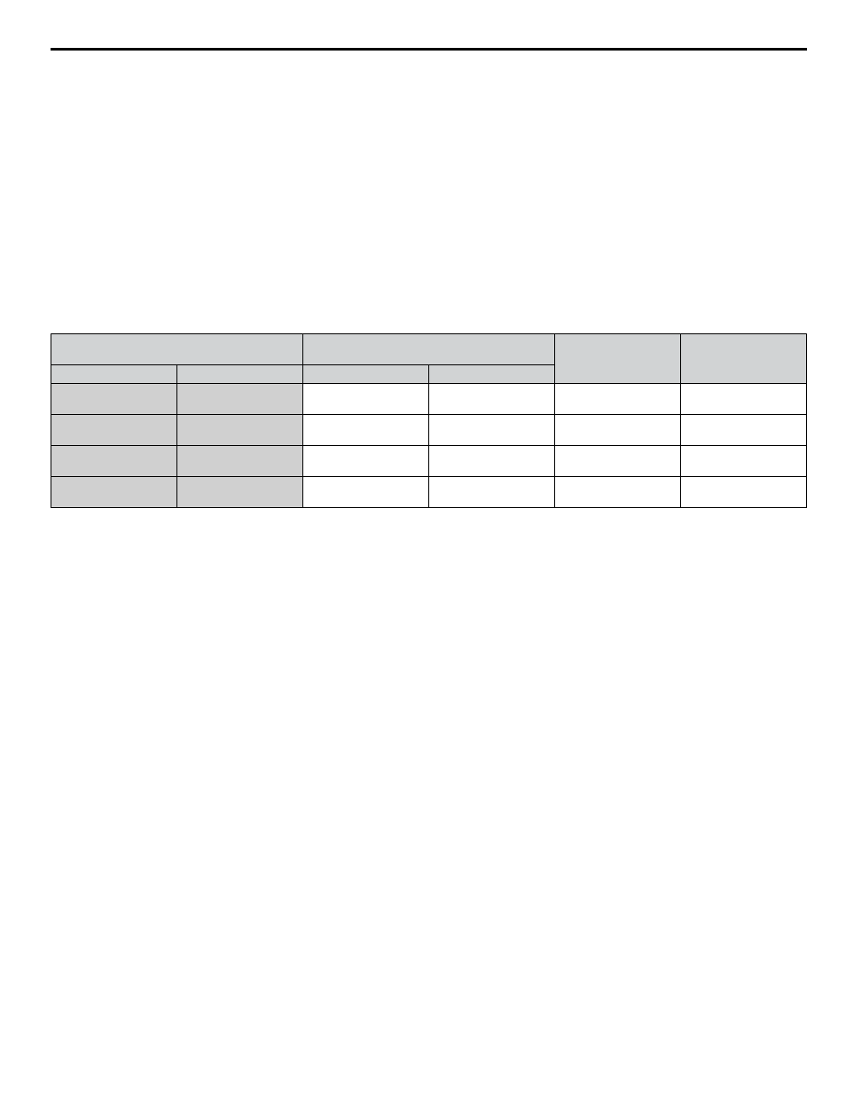
Table i.33 Safety Input and EDM Terminal Status
Safe Disable Input Status
Safe Disable Status Monitor,
(DM+, DM-)
Drive Output Status
Digital Operator
Display
Input 1, H1-HC
Input 2, H2-HC
S6 Switch = “N.O.”
S6 Switch = “N.C.”
OFF
OFF
OFF
ON
Safely disabled,
“Safe Torque Off”
Hbb (flashes)
ON
OFF
ON
OFF
Safely disabled,
“Safe Torque Off”
HbbF (flashes)
OFF
ON
ON
OFF
Safely disabled,
“Safe Torque Off”
HbbF (flashes)
ON
ON
ON
OFF
Baseblock,
ready for operation
Normal display
Safe Disable Status Monitor
Slide Switch S6 controls the polarity of this signal. Refer to
for functionality.
With the Safe Disable monitor output (terminals DM+ and DM-), the drive provides a safety status feedback signal. This signal
should be read by the device that controls the Safe Disable inputs (PLC or a safety relay) in order to prohibit leaving the “Safe
Torque Off” status in case the safety circuit malfunctions. Refer to the instruction manual of the safety device for details on
this function.
Digital Operator Display
When both Safe Disable inputs are open, “Hbb” will flash in the digital operator display.
If one Safe Disable channel is on while the other is off, “HbbF” will flash in the display to indicate that there is a problem in
the safety circuit or in the drive. This display should not appear under normal conditions if the Safe Disable circuit is utilized
properly.
If a fault in the safety circuit of the drive is detected, “SCF” will be displayed in the LCD operator. This indicates damage to
the drive.
n
Validating Safe Disable Function
Always perform the following validation test on the safe disable inputs after completing the wiring after start-up, when
replacing parts, or when conducting maintenance. Maintain check results as a record of tests performed.
• When the H1 and H2 signals turn OFF, confirm that “Hbb” is displayed on the LCD operator, and that the motor is not in
operation.
• Monitor the ON/OFF status of the H1 and H2 signals and confirm the EDM signal according to
If the ON/OFF status of the signals do not match the display, it is possible that there is an error in the external device, the
external wiring is disconnected, there is a short circuit in the external wiring, or a failure in the drive. Find the cause and correct
the problem.
• In normal operation, confirm the EDM signal according to
i.9 Standards Compliance
YASKAWA ELECTRIC TOEP C710636 04C U1000 Industrial MATRIX Drive Quick Start Guide
91