Parameter table, I.8 parameter table – Yaskawa U1000 Industrial MATRIX Drive User Manual
Page 77
i.8
Parameter Table
This parameter table shows the most important parameters. Default settings are in bold type. Refer to the Technical Manual
for a complete list of parameters.
No.
Name
Description
A1-02
Control Method
Selection
0: V/f Control
1: V/f Control with PG
2: Open Loop Vector Control
3: Closed Loop Vector Control
5: Open Loop Vector Control for PM
6: Advanced Open Loop Vector Control for
PM
7: Closed Loop Vector Control for PM
A1-03
Initialize Parameters
0: No initialization
1110: User Initialize (parameter values
must be stored using parameter o2-03)
2220: 2-Wire initialization
3330: 3-Wire initialization
5550: oPE04 error reset
A1-06
Application Preset
0: General-purpose
1: Water supply pump
2: Conveyor
3: Exhaust fan
4: HVAC fan
5: Air compressor
b1-01
Frequency Reference
Selection 1
0: Digital operator
1: Analog input terminals
2: MEMOBUS/Modbus communications
3: Option PCB
4: Pulse train input (terminal RP)
b1-02
Run Command
Selection 1
0: Digital operator
1: Digital input terminals
2: MEMOBUS/Modbus communications
3: Option PCB
b1-03
Stopping Method
Selection
0: Ramp to stop
1: Coast to stop
2: DC Injection Braking to stop
3: Coast with timer
b1-04
Reverse Operation
Selection
0: Reverse enabled.
1: Reverse disabled.
C1-01
Acceleration Time 1
Sets the time to accelerate from 0 to
maximum frequency.
C1-02
Deceleration Time 1
Sets the time to decelerate from maximum
frequency to 0.
C2-01
S-Curve Characteristic
at Accel Start
S-curve at acceleration start.
C2-02
S-Curve Characteristic
at Accel End
S-curve at acceleration end.
C2-03
S-Curve Characteristic
at Decel Start
S-curve at deceleration start.
C2-04
S-Curve Characteristic
at Decel End
S-curve at deceleration end.
C6-01
Drive Duty Selection
0: Heavy Duty (HD)
Overload capability: 150% of drive rated
Heavy Duty current for 60 s
Default Carrier Frequency: 2 kHz
1: Normal Duty (ND)
Overload capability: 120% of drive rated
Normal Duty current for 60 s
Default Carrier Frequency: 2 kHz Swing
PWM
No.
Name
Description
C6-02
Carrier Frequency
Selection
1: 4.0 kHz
2: 6.0 kHz
3: 8.0 kHz
4: 10.0 kHz
F: User-defined (determined by C6-03 to
C6-05)
Default setting value is determined by
A1-02, Control Method Selection, C6-01,
Drive Duty Selection, and o2-04, Drive
Model Selection.
C7-60
Output Voltage Limit
Mode Selection
0: Harmonic suppression priority mode
1: High output voltage mode
d1-01 to
d1-16
Frequency Reference 1
to 16
Sets the frequency reference for the drive.
Setting units are determined by parameter
o1-03.
d1-17
Jog Frequency
Reference
Sets the Jog frequency reference. Setting
units are determined by parameter o1-03.
d2-01
Frequency Reference
Upper Limit
Sets the frequency reference upper limit as
a percentage of the maximum output
frequency.
d2-02
Frequency Reference
Lower Limit
Sets the frequency reference lower limit as
a percentage of the maximum output
frequency.
E1-03
V/f Pattern Selection
0: 50 Hz, Constant torque 1
1: 60 Hz, Constant torque 2
2: 60 Hz, Constant torque 3 (50 Hz base)
3: 72 Hz, Constant torque 4 (60 Hz base)
4: 50 Hz, Variable torque 1
5: 50 Hz, Variable torque 2
6: 60 Hz, Variable torque 1
7: 60 Hz, Variable torque 2
8: 50 Hz, High starting torque 1
9: 50 Hz, High starting torque 2
A: 60 Hz, High starting torque 3
B: 60 Hz, High starting torque 4
C: 90 Hz (60 Hz base)
D: 120 Hz (60 Hz base)
E: 180 Hz (60 Hz base)
F: Custom V/f, E1-04 through E1-13
settings define the V/f pattern
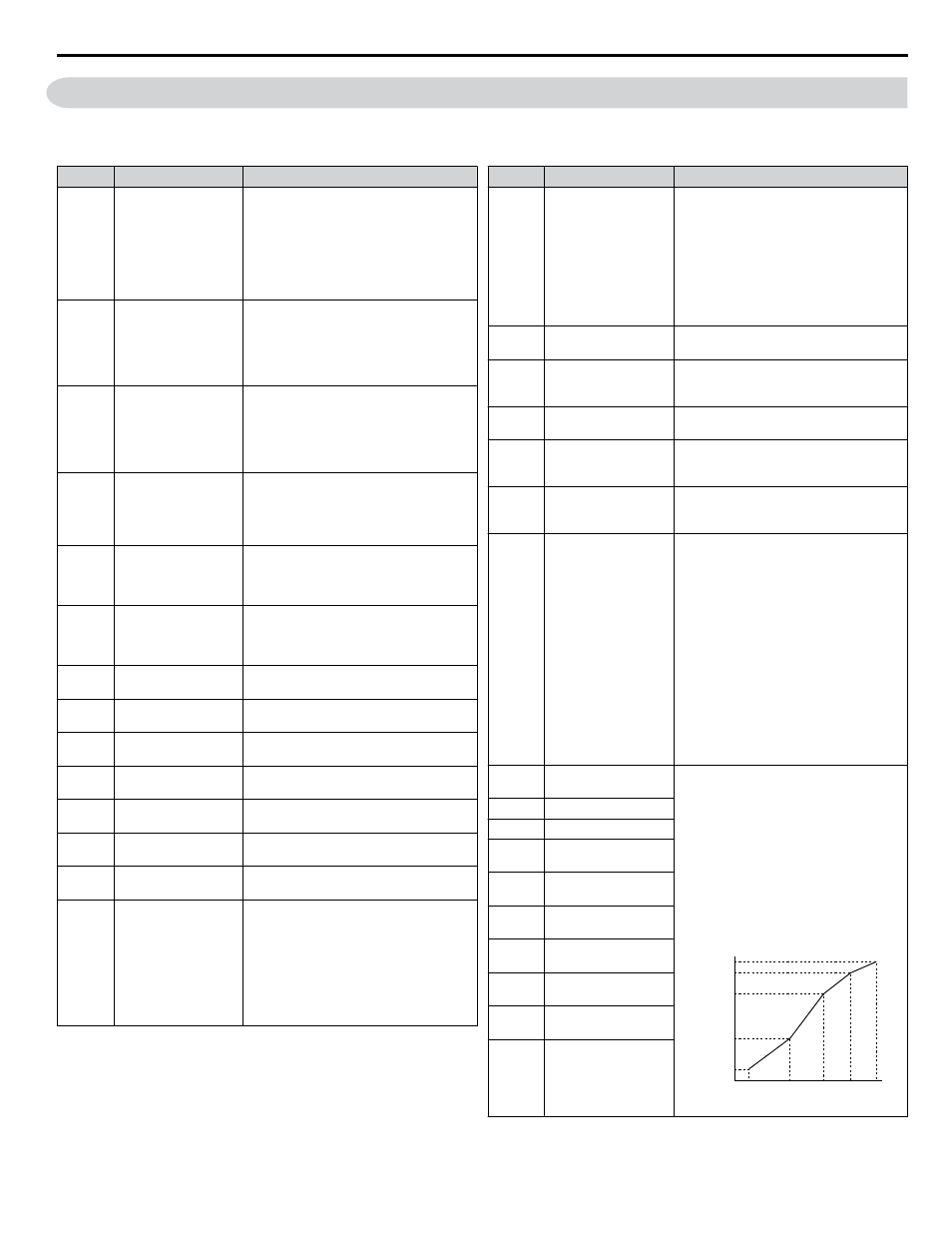
E1-04
Maximum Output
Frequency
Parameters E1-04 and E1-06 to E1-13 can
only be changed when E1-03 is set to F.
To set linear V/f characteristics, set the
same values for E1-07 and E1-09.
In this case, the setting for E1-08 will be
disregarded. Ensure that the five
frequencies are set according to the
following rules to prevent triggering an
oPE10 fault:
E1-09 ≤ E1-07 < E1-06 ≤ E1-11 ≤ E1-04
Setting E1-11 to 0 disables both E1-11 and
E1-12 and the above conditions do not
apply.
Output Voltage (V)
Frequency (Hz)
E1-05
E1-12
E1-13
E1-08
E1-10
E1-09
E1-07 E1-06 E1-11 E1-04
E1-05
Maximum Voltage
E1-06
Base Frequency
E1-07
Middle Output
Frequency
E1-08
Middle Output
Frequency Voltage
E1-09
Minimum Output
Frequency
E1-10
Minimum Output
Frequency Voltage
E1-11
Middle Output
Frequency 2
E1-12
Middle Output
Frequency Voltage 2
E1-13
Base Voltage
i.8 Parameter Table
YASKAWA ELECTRIC TOEP C710636 04C U1000 Industrial MATRIX Drive Quick Start Guide
77