D2-01: frequency reference upper limit, D2-02: frequency reference lower limit, E2-01: motor rated current – Yaskawa U1000 Industrial MATRIX Drive User Manual
Page 57
n
d2-01: Frequency Reference Upper Limit
Sets the maximum frequency reference as a percentage of the maximum output frequency. This limit applies to all frequency
references.
Even if the frequency reference is set to a higher value, the drive internal frequency reference will not exceed this value.
No.
Parameter Name
Setting Range
Default
d2-01
Frequency Reference Upper Limit
0.0 to 110.0%
100.0%
n
d2-02: Frequency Reference Lower Limit
Sets the minimum frequency reference as a percentage of the maximum output frequency. This limit applies to all frequency
references.
If a lower reference than this value is entered, the drive will run at the limit set to d2-02. If the drive is started with a lower
reference than d2-02, it will accelerate up to d2-02.
No.
Parameter Name
Setting Range
Default
d2-02
Frequency Reference Lower Limit
0.0 to 110.0%
0.0%
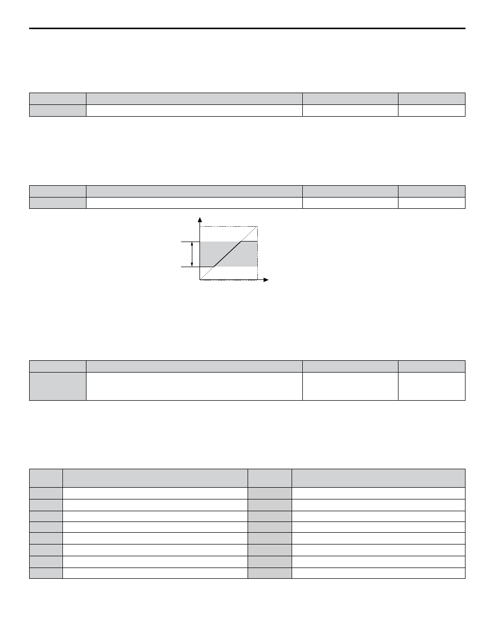
Internal frequency
reference
d2-01
Operating
range
Frequency Reference Upper Limit
Set frequency reference
Frequency Reference Lower Limit
d2-02
Figure i.45 Frequency Reference: Upper and Lower Limits
n
E2-01: Motor Rated Current
Provides motor control, protects the motor, and calculates torque limits. Set E2-01 to the full load amps (FLA) stamped on
the motor nameplate. If Auto-Tuning completes successfully, the value entered to T1-04 will automatically be saved to E2-01.
No.
Parameter Name
Setting Range
Default
E2-01
Motor Rated Current
10% to 150% of the drive
rated current
<1>
Determined by
C6-01 and o2-04
<1> Display is in the following units:
2o0028, 2o0042, and 4o0011 to 4o0027: 0.01 A units.
2o0054 to 2o0248 and 4o0034 to 4o0414: 0.1 A units.
Note:
An oPE02 error will occur if the motor rated current in E2-01 is set lower than the motor no-load current in E2-03. Set E2-03 correctly to
prevent this error.
n
H1-01 to H1-08: Functions for Terminals S1 to S8
No.
Parameter Name
Setting
Range
Default
H1-01
Multi-Function Digital Input Terminal S1 Function Selection
1 to 9F
40 (F)
<1>
: Forward Run Command (2-Wire sequence)
H1-02
Multi-Function Digital Input Terminal S2 Function Selection
1 to 9F
41 (F)
<1>
: Reverse Run Command (2-Wire sequence)
H1-03
Multi-Function Digital Input Terminal S3 Function Selection
0 to 9F
24: External Fault (N.O., always detected, coast to stop)
H1-04
Multi-Function Digital Input Terminal S4 Function Selection
0 to 9F
14: Fault Reset
H1-05
Multi-Function Digital Input Terminal S5 Function Selection
0 to 9F
3 (0)
<1>
: Multi-Step Speed Reference 1
H1-06
Multi-Function Digital Input Terminal S6 Function Selection
0 to 9F
4 (3)
<1>
: Multi-Step Speed Reference 2
H1-07
Multi-Function Digital Input Terminal S7 Function Selection
0 to 9F
6 (4)
<1>
: Jog Reference Selection
H1-08
Multi-Function Digital Input Terminal S8 Function Selection
0 to 9F
8: External Baseblock Command
<1> Number appearing in parenthesis is the default value after performing a 3-Wire initialization (A1-03 = 3330).
i.5 Start-Up Programming and Operation
YASKAWA ELECTRIC TOEP C710636 04C U1000 Industrial MATRIX Drive Quick Start Guide
57