SMA SUNNY HOME MANAGER Installation User Manual
Page 43
SMA Solar Technology AG
7 Connection
Installation Manual
HoMan-IA-en-17
43
3. Write down the color of the insulated conductors:
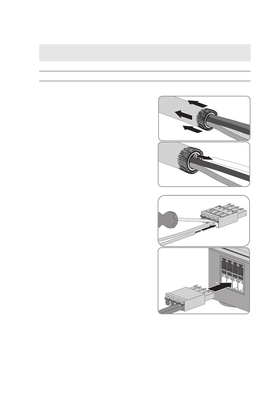
4. Remove 4 cm of the cable sheath at the other end of the cable.
5. Shorten the cable shield to approximately 5 mm.
Fold the surplus cable shield back onto the cable
sheath.
6. Shorten unused insulated conductors flush with the
cable sheath.
7. Strip the insulated conductors by 6 mm.
8. Release the pin connectors of the four-pole plug
with a screwdriver. Insert the DC − insulated
conductor into contact pin 3 and the DC+ insulated
conductor into contact pin 4 of the four-pole plug.
9. If no energy meter is connected to the four-pole
plug, insert the four-pole plug into the lower contact
pin row of any one of the pin connectors on the
Sunny Home Manager.
10. If an energy meter is connected to the four-pole
plug, insert the four-pole plug into the lower contact
pin row of the pin connector assigned to the given
energy meter (see Section 7.1 "Connection Area",
page 34).
11. Connect the AC connection cable to the top-hat rail power supply (see manual of the top-hat
rail power supply).
Terminals on the top-hat rail
power supply
Insulated conductor color
DC+
DC −