Interface – SMA SUNNY HOME MANAGER Installation User Manual
Page 38
7 Connection
SMA Solar Technology AG
38
HoMan-IA-en-17
Installation Manual
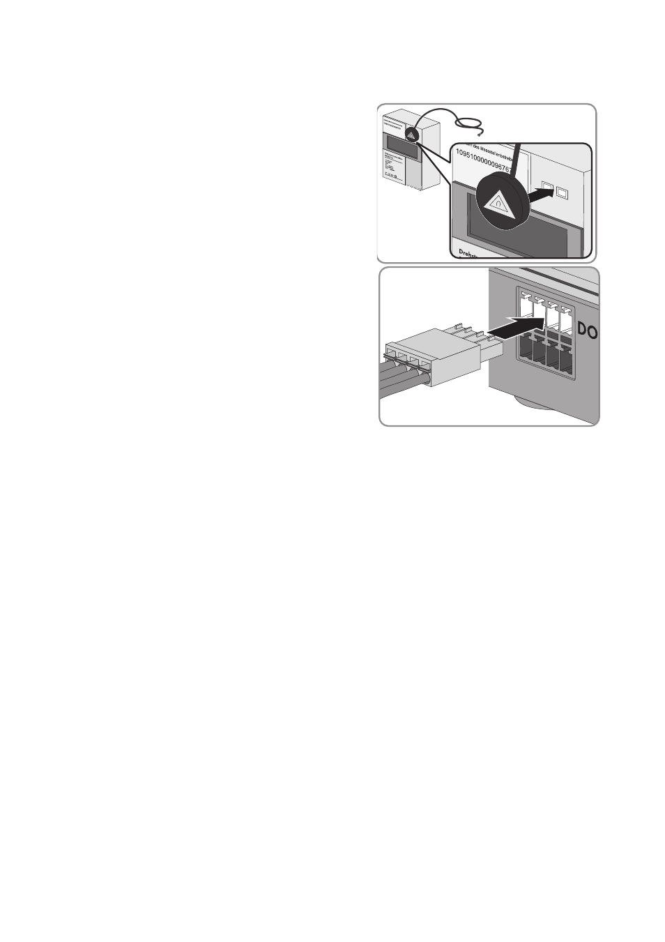
Procedure
1. Position the magnet retainer of the optical probe at
the front upper right-hand corner of the energy
meter. The infrared interfaces on the optical probe
and on the energy meter must be perfectly aligned.
2. Connect the plug of the optical probe to the pin
connector to which the corresponding energy meter
is assigned. Insert the four-pole plug into the upper
contact pin row:
• For purchased electricity meters, insert the
four-pole plug into the pin connector Meter 1.
• For feed-in meters, insert the four-pole plug into
the pin connector Meter 2.
• For PV production meters, insert the four-pole
plug into the pin connector Meter 3.
• For bidirectional meters for grid feed-in and purchased electricity, insert the four-pole plug
into the pin connector Meter 1.
3. Use the labels provided to mark each cable with the pin connector and energy meter to which
it is assigned.
7.2.3 Connecting the Sunny Home Manager to Energy Meters
with S0 Interface
Additionally required material (not included in the scope of delivery):
☐ 1 cable with at least 2 insulated conductors
Cable requirements:
☐ Conductor cross-section: 0.2 mm
2
to 1.5 mm
2
☐ Maximum cable length: 30 m
Requirements for energy meters with an S0 interface:
☐ S0 interface in accordance with DIN EN 62053-31, class A
☐ Bidirectional meters with an S0 interface must be equipped with two S0 interfaces.
☐ Energy meters with an S0 interface must output values netted across the line phases at the S0
interface. If necessary, contact the manufacturer of the energy meter.
☐ Recommended pulse length: at least 20 ms