Graphical display of turning operations – HEIDENHAIN TNC 640 (34059x-04) ISO programming User Manual
Page 431
Basis Functions (Software Option 50) 14.2
14
TNC 640 | User's Manual for DIN/ISO Programming | 3/2014
431
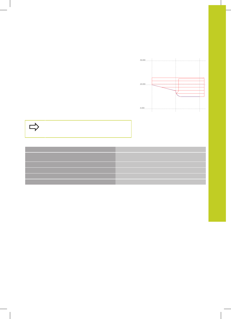
Graphical display of turning operations
You can graphically simulate turning processes with the line graphic
in Programming operating mode. The requirement for this is a
workpiece blank definition suitable for the turning process.
The assignment of the axes with turning is defined so that the
X coordinates describe the diameter of the workpiece and the
Z coordinates the longitudinal positions. To display the traverse
movements in Turning mode you must use a workpiece blank
definition with the spindle axis
Y.
Even when turning occurs in a 2D plane (X and Z coordinates) you
must still program the Y values when defining the workpiece blank.
The TNC requires the Y expansion for calculating the workpiece
blank cuboid. It is sufficient when you enter small values here
such as -1 and +1, as the Y coordinates in Turning mode are not
considered as the operating axis.
In the Program Test operating mode, you can only
use the 3D line graphic for simulating processing in
Turning mode.
NC syntax
%LT 200 G71 *
N10 G30 G18 X+0 Y-1 Z-50 *
Define the workpiece blank for graphic workpiece
simulation
N20 G31 G90 X+87 Y+1 Z+2 *
N30 T301 *
Tool call
N40 G00 G40 G90 Z+250 *
Retract the tool in the spindle axis at rapid traverse
N50 FUNCTION MODE TURN *
Activate Turning mode