Defining a workpiece blank, Programming the first part 1.3 – HEIDENHAIN TNC 620 (81760x-02) ISO programming User Manual
Page 51
Programming the first part
1.3
1
TNC 620 | User's ManualDIN/ISO Programming | 2/2015
51
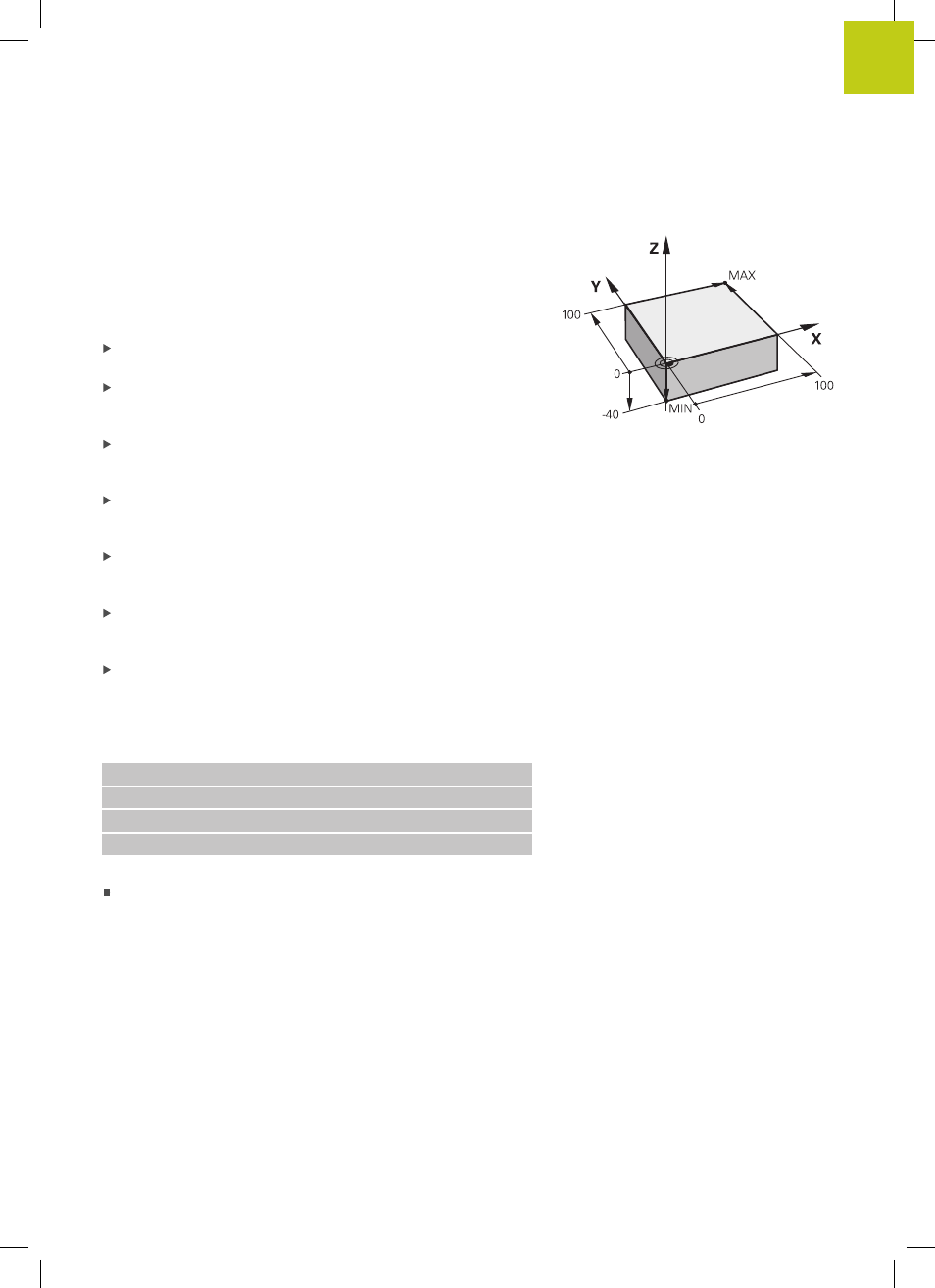
Defining a workpiece blank
After you have created a new program you can define a workpiece
blank. For example, define a cuboid by entering the MIN and MAX
points, each with reference to the selected reference point.
After you have selected the desired blank form via soft key, the
TNC automatically initiates the workpiece blank definition and asks
for the required data:
Spindle axis Z – Plane XY: Enter the active spindle axis. G17 is
saved as default setting. Accept with the
ENT key
Workpiece blank def.: Minimum X: Enter the smallest X
coordinate of the workpiece blank with respect to the reference
point, e.g. 0, confirm with the
ENT key
Workpiece blank def.: Minimum Y: Smallest Y coordinate of
the workpiece blank with respect to the reference point, e.g. 0.
Confirm with the
ENT key
Workpiece blank def.: Minimum Z: Smallest Z coordinate of
the workpiece blank with respect to the reference point, e.g.
-40, confirm with the
ENT key
Workpiece blank def.: Maximum X: Enter the largest X
coordinate of the workpiece blank with respect to the reference
point, e.g. 100, confirm with the
ENT key
Workpiece blank def.: Maximum Y: Enter the largest Y
coordinate of the workpiece blank with respect to the reference
point, e.g. 100. Confirm with the
ENT key
Workpiece blank def.: Maximum Z: Enter the largest Z
coordinate of the workpiece blank with respect to the reference
point, e.g. 0. Confirm with the
ENT key. The TNC concludes the
dialog
Example NC blocks
%NEW G71 *
N10 G30 G17 X+0 Y+0 Z-40 *
N20 G31 X+100 Y+100 Z+0 *
N99999999 %NEW G71 *
Further information on this topic
Defining the workpiece blank: page 100