Centric polygon milling—roughing g843, 1 1 din plus (y axis): milling cy cles – HEIDENHAIN CNC Pilot 4290 V7.1 Description of B and Y axes User Manual
Page 54
54
1
.1
1
DIN PLUS (Y Axis): Milling Cy
cles
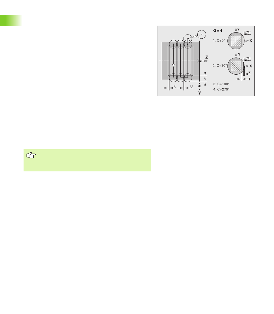
Centric polygon milling—roughing G843
G843 roughs centric polygons defined with G477 Geo (XY plane) or
G487 Geo (YZ plane). The cycle mills from the outside toward the
inside. The tool moves to the working plane outside of the workpiece
material.
Parameters
NS
Block number—reference to the contour description
P
(Maximum) milling depth (infeed in the working plane)
I
Oversize in X direction
K
Oversize in Z direction
U
(Minimum) overlap factor. Defines the overlap of milling paths
(default: 0.5).
Overlap = U*milling diameter
V
Overrun factor. Defines the distance by which the tool should
pass the outside radius of the workpiece (default: 0.5).
Overrun = V*milling diameter
F
Feed rate for infeed (default: active feed rate)
J
Return plane (default: back to starting position)
XY plane: Retraction position in Z direction
YZ plane: Retraction position in X direction (diameter)
Oversizes are taken into account:
G57: Oversize in X, Z direction
G58: Equidistant oversize in the milling plane
Cycle run
1
Starting position (X, Y, Z, C) is the position before the cycle
begins.
2
Calculate the proportioning of cuts (infeeds to the milling planes,
infeeds in the milling depths) and the spindle positions.
3
Spindle turns to the first position. The tool moves to the safety
clearance and plunges to the first milling depth.
4
Mill the first plane.
5
Retract by the safety clearance, return and cut to the next milling
depth.
6
Repeat steps 4 and 5 until the complete area is milled.
7
The tool returns to “retraction plane J.” The spindle turns to the
next position. The tool moves to the safety clearance and plunges
to the first milling depth.
8
Repeat steps 4 to 7 until all polygonal surfaces are milled.
9
Return to “retraction plane J.”