3 programming notes, Milling contour position, Cutting limit – HEIDENHAIN CNC Pilot 4290 V7.1 Description of B and Y axes User Manual
Page 20
20
1
.3 Pr
ogr
a
mming Not
e
s
1.3 Programming Notes
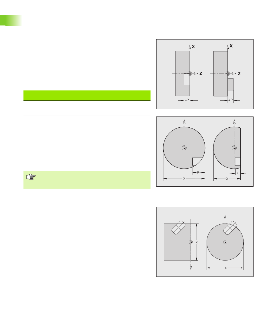
Milling contour position
Define the reference plane or the reference diameter in the section
code. Specify the depth and position of a milling contour (pocket,
island) in the contour definition:
With depth P programmed in the previous G308 cycle.
Alternatively on figures: Cycle parameter depth P.
The algebraic sign of “P” defines the position of the milling contour:
P<0: Pocket
P>0: Island
X: Reference diameter from the section code
Z: Reference plane from the section code
P: Depth from G308 or from the figure definition
Cutting limit
If parts of the milling contour lie outside of the turning contour, you
must limit the machining area with the area diameter X / reference
diameter X (parameters of the section code or of the figure
definition).
The cutting limits are also effective when milling in a tilted plane.
Milling contour position
Section
P
Surface
Milling floor
STIRN [FRONT]
P<0
P>0
Z
Z+P
Z+P
Z
RUECKSEITE
[REAR SIDE]
P<0
P>0
Z
Z–P
Z–P
Z
MANTEL
[SURFACE]
P<0
P>0
X
X+(P*2)
X+(P*2)
X
The area milling cycles mill the surface specified in the
contour definition. Islands within this surface are not
taken into consideration.