10 din plus: linear and circular paths, Milling: linear movement g1 – HEIDENHAIN CNC Pilot 4290 V7.1 Description of B and Y axes User Manual
Page 49
HEIDENHAIN CNC PILOT 4290
49
1
.1
0
DIN PLUS: Linear and Cir
c
ular P
a
ths
1.10 DIN PLUS: Linear and Circular
Paths
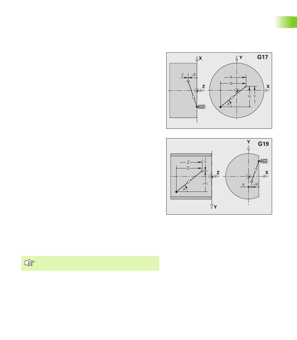
Milling: Linear movement G1
G1 moves the tool on a linear path at the feed rate to the “end point.”
The execution of G1 varies depending on the working plane:
G17 Interpolation in the XY plane
Infeed in Z direction
Angle A—reference: positive X axis
G18 Interpolation in the XZ plane
Infeed in Y direction
Angle A—reference: negative Z axis
G19 Interpolation in the YZ plane
Infeed in X direction
Angle A—reference: positive Z axis
Parameters
X
End point (diameter)
Y
End point
Z
End point
A
Angle (reference: depends on the working plane)
Q
Point of intersection. End point if the line segment intersects
a circular arc (default: 0):
Q=0: Near point of intersection
Q=1: Far point of intersection
B
Chamfer/rounding. Defines the transition to the next contour
element. When entering a chamfer/rounding, program the
theoretical end point.
No entry: Tangential transition
B=0: No tangential transition
B>0: Rounding radius
B<0: Chamfer width
E
Special feed factor for the chamfer/rounding (default: 1)
Special feed rate = active feed rate * E (0 < E <= 1)
Programming X, Y, Z: Absolute, incremental or
modal or “?”