I - 1 fundamentals of positioning – HEIDENHAIN PT 855 for Milling User Manual
Page 9
I - 1 Fundamentals of Positioning
Fundamentals of Positioning
POSITIP 855
Operating Instructions
7
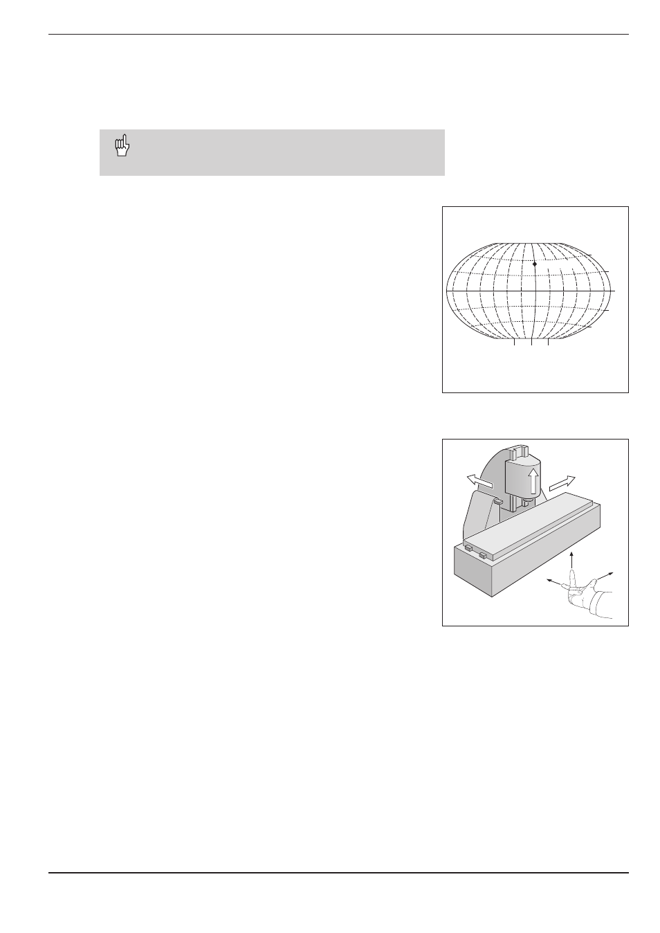
Fig. 2: Designations and directions of the axes
on a milling machine
Fig. 1: The geographic coordinate system is an
absolute reference system
I - 1
Fundamentals of Positioning
You can skip over this chapter if you are familiar with the
concepts of coordinate systems, incremental and absolute
dimensions, nominal and actual positions, and distance-to-go.
0° 90°
90°
0°
30°
30°
60°
60°
Greenwich
+X
+Y
+Z
+X
+Z
+Y
On a milling machine equipped with a position display unit, work-
pieces are normally machined according to a workpiece-based Car-
tesian coordinate system (a rectangular coordinate system named
after the French mathematician and philosopher Renatus Cartesius,
who lived from 1596 to 1650). The Cartesian coordinate system is
based on three coordinate axes designated X, Y and Z which are
parallel to the machine guideways.
The figure to the right illustrates the "right-hand rule" for remember-
ing the three axis directions: the middle finger is pointing in the posi-
tive direction of the tool axis from the workpiece toward the tool (the
Z axis), the thumb is pointing in the positive X direction, and the in-
dex finger in the positive Y direction.
Coordinate systems
In order to define positions on a surface, a reference system is
required. For example, positions on the earth's surface can be
defined absolutely by their geographic coordinates of longitude and
latitude. The term coordinate comes from the Latin word for "that
which is arranged." In contrast to the relative definition of a posi-
tion that is referenced to a known location, the network of horizon-
tal and vertical lines on the globe constitute an absolute reference
system.