HEIDENHAIN PT 855 for Milling User Manual
Page 103
II - 4 Data Interface
POSITIP 855
Technical Information
101
Start bit
7 data bits
Parity bit
2 stop bits
Fig. 44: Data transfer format
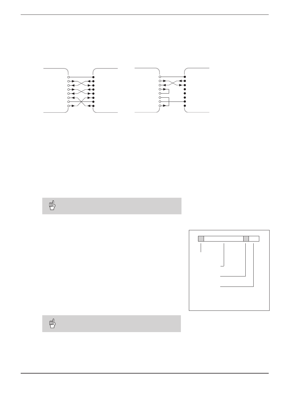
Wiring the connecting cable
The wiring of the connecting cable depends on the device being
connected (see technical documentation for external device).
Full wiring
Simplified wiring
1
1
GND
2
3
4
5
6
20
7
TXD
RXD
RTS
CTS
DSR
GND
SIGNAL
DTR
CHASSIS
2
3
4
5
6
20
7
PT 855
GND
TXD
RXD
RTS
CTS
DSR
GND
SIGNAL
DTR
CHASSIS
1
GND
2
3
4
5
6
20
7
TXD
RXD
RTS
CTS
DSR
GND
SIGNAL
DTR
CHASSIS
1
GND
2
3
4
5
6
20
7
TXD
RXD
RTS
CTS
DSR
GND
SIGNAL
DTR
CHASSIS
PT 855
Fig. 42: Diagram for full wiring Fig. 43: Diagram for simplified wiring
Setting the baud rate: P 50
The data interfaces on the POSITIP and on the external device must
be set to the same baud rate. The external device must be capable
of processing the selected baud rate.
The baud rate for the data interface on the POSITIP is set with an
operating parameter.
The machine manufacturer can also make this parameter available
as a user parameter (see I - 7).
Settings for the baud rate
P 50 = 110, 150, 300, 600, 1200, 2400
4800, 9600, 19 200, 38 400 [baud]
The baud rate for data transfer between POSITIP and
the FE 401 Floppy Disk Unit is always 9600.
Data format
Data are transferred in the following sequence:
1. Start bit
2. Seven data bits
3. Parity bit (even parity)
4. Two stop bits
Interrupting data transfer
There are two ways to interrupt data transfer from the external de-
vice and restart it:
➤
Start/Stop over input RXD
DC3 = XOFF = CTRL S: interrupt data transfer
DC1 = XON = CTRL Q: resume data transfer
➤
Start/Stop over control line CTS
When the stop signal CTS or DC3 has been received,
POSITIP sends up to two further characters.
S D D D D D D D P S S