Ii - 6 switching inputs and outputs – HEIDENHAIN PT 855 for Milling User Manual
Page 109
II - 6 Switching Inputs and Outputs
POSITIP 855
Technical Information
107
II - 6
Switching Inputs and Outputs
Switching signals at the D-sub connection EXT allow you to
reset the actual value display of a coordinate axis to zero
control motor cutoff
start measured value output (see chapter II - 5)
Interface X41 (EXT) complies with the recom-
mendations in EN 50 178 for separation from
line power.
The outputs for the switching ranges are me-
tallically isolated from the device electronics by
means of optocouplers.
Danger to internal components!
Voltage from external circuitry must conform
to the recommendations in VDE 0100, Part 410
for low-voltage electrical separation.
Connect inductive loads such as relays only with
a quenching diode. Shield against electromag-
netic fields. Connect with a shielded cable with
the shield extended to the connector housing.
Pin layout of D-sub connection EXT (X41)
Pin
Assignment
10
0 V for switching range
23, 24, 25
24 V DC for switching range
11
POSITIP ready for operation
14
Display value outside of switching range 0
15
Display value outside of switching range 1
16
Display value outside of switching range 2
17
Display value outside of switching range 3
18
Display value outside of switching range 4
19
Display value outside of switching range 5
20
Display value outside of switching range 6
21
Display value outside of switching range 7
1
0 V (internal)
2
Reset axis 1 to zero
3
Reset axis 2 to zero
4
Reset axis 3 to zero
5
Reset axis 4 to zero
8
Pulse: output measured value
9
Contact: output measured value
6, 7, 12,
Do not use
13, 22
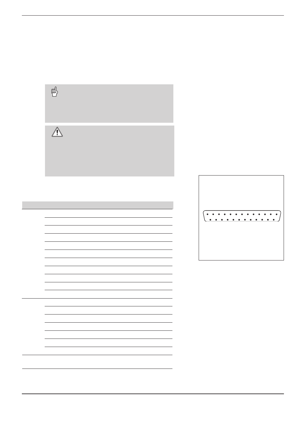
Fig. 48: The D-sub connection EXT
1
6
2
7
3
8
5
4
9
14
15
16
17
18
19
20
21
10
11
12
13
22
23
24
25
O
utputs
Inputs