HEIDENHAIN PT 855 for Milling User Manual
Page 105
II - 5 Measured Value Output
POSITIP 855
Technical Information
103
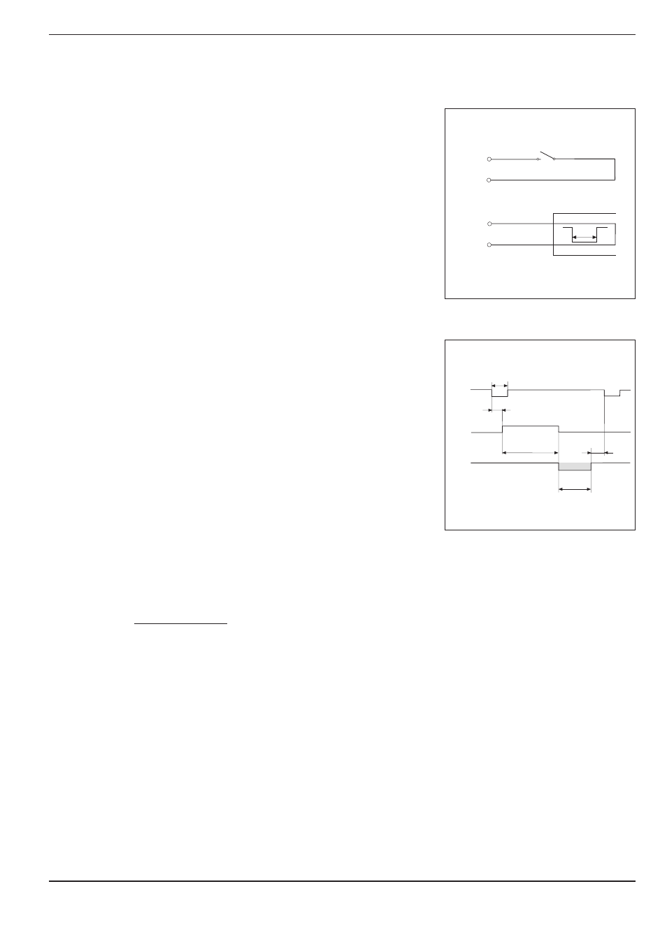
Fig.47: Time diagram for measured value
output over external switching input
Starting measured value output over external switching input
You can start start measured value output over the switching input
at the D-sub connection EXT by sending a pulse or by making
contact.
Contact at pin 9: make contact against 0 V
Pulse at pin 8: pulse duration t
e
³ 1.2 µs
The contact or pulse can also be sent over a TTL logic device
(such as SN 74 LS XX):
U
H
³ 3.9 V (U
MAX
= 15 V)
U
L
£ 0.9 V with I
L
£ 6 mA
Starting measured value output
E X T
P I N 9
P I N 1
( 0 V )
P I N 8
P I N 1
( 0 V )
t
e
E X T
t
1
t
3
t
2
t
D
t
e
T X D
Fig.46: Signal by make contact against 0 V or
by pulse
t
e
: Minimum duration, pulse
t
e
³ 1.2 ms
t
e
: Minimum duration, contact
t
e
³ 7 ms
t
1
: Delay between pulse and internal latch
t
1
£ 0.8 µs
t
1
: Delay between contact and internal latch
t
1
£ 4.5 ms
t
2
: Delay between internal latch and measured value output
t
2
£ 30 ms + (5 ms · N)
N = number of rotary axes with Deg/Min/Sec display
t
3
: Delay between end of data output and next latch over
external switching input
t
3
³ 0 ms
t
D
: Duration of measured value output
The duration of measured value output (t
D
) depends on:
The selected baud rate (BR)
The number of axes (M)
The number of blank lines (L)
t
D
=
[s]
BR
176 · M + L · 11