Robotic pan/tilt head, Camera/lens assembly, Eps and – Grass Valley Ignite SDC User Manual
Page 31: Figure 13
Ignite SDC/HDC Robotic Camera Instruction Manual
31
System Interconnection
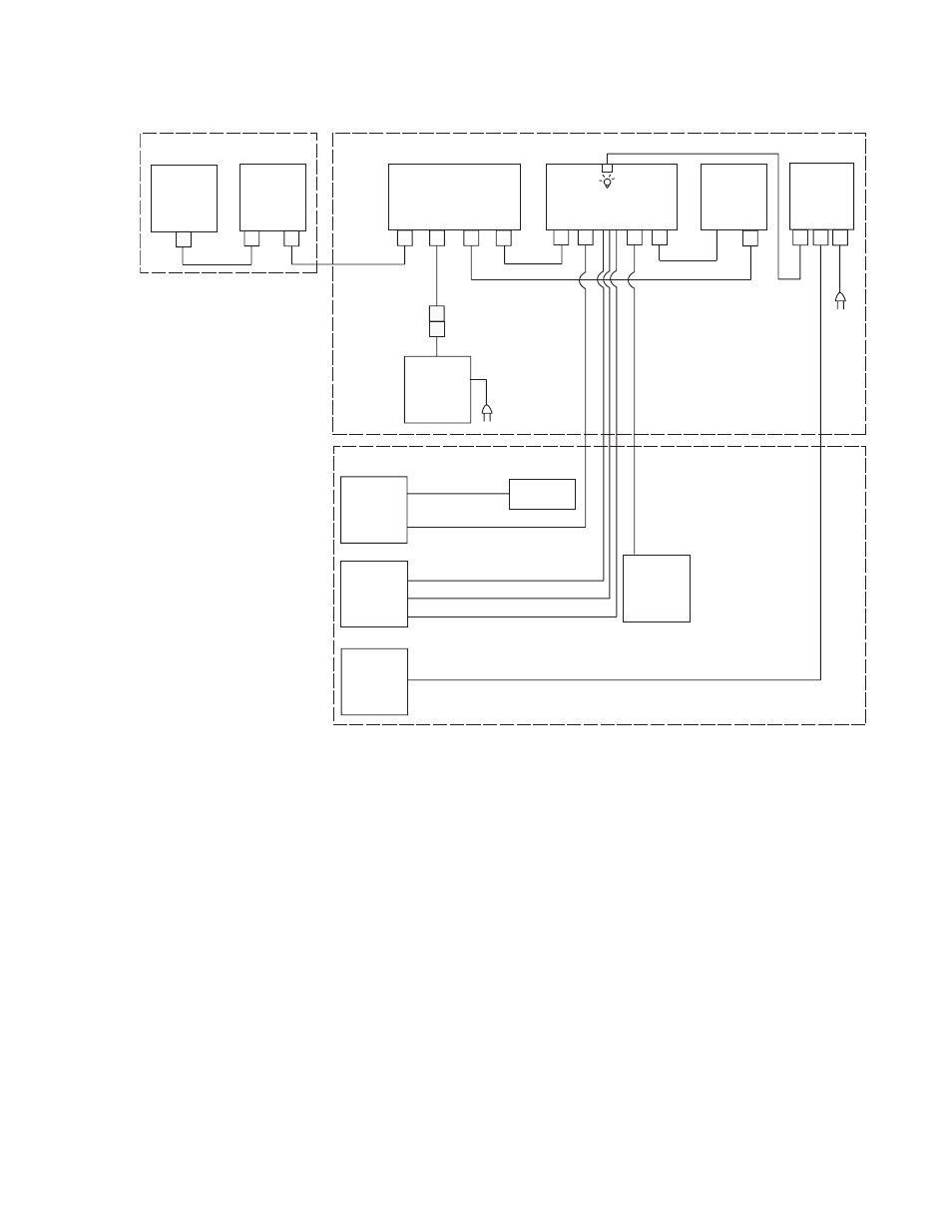
Figure 13. Interconnect (without Iignite System) Diagram
WARNING
Ensure mains power is OFF before connecting or disconnecting any
cables, cords, or wires.
Robotic Pan/Tilt Head
1.
Connect a CAT-5 cable (not supplied) between the pan/tilt head
assembly and the subnet hub.
2.
Connect the zoom/focus cable hirose circular connector to the lens
assembly and the DB-9 connector to the pan/tilt head.
Camera/Lens Assembly
1.
Connect the camera control and power harness from the camera block
to the pan/tilt head (DB15).
SHOT
DIRECTOR
PAN/TILT
HEAD
LENS
ZOOM/FOCUS
POWER
IRIS
VIDEO
IP CONTROL
SUBNET
HUB
48 VDC PWR
SUPPLY
AMP CIRC
CAM
CTRL/PWR
ZOOM/FOCUS
GEN-LOCK
(FACILITY
PROVIDED)
CA
T-5
DB9
CAMERA
BLOCK
DB15
VID OUT
CA
T-5
CA
T-5
CA
T-5
HARD
WIRED
HIROSE CIRC
IP CONTROL
G/L BNC
HIROSE CIRC
HD15/
SCSI-50
HARD
WRED
DIN8
HARD
WRED
SHOT
DIRECTOR
SDC/HDC ROBOTIC CAMERA
VIDEO
MONITOR
VIDEO
SWITCH
TALLY
CTRLR
VIDEO
AUX
OUT
PREV
PROG
RED (PROGRAM) TALLY
AMBER (PREVIEW) TALLY
VIDEO
FACILITY PROVIDED
EQUIPMENT
PROMPTER
POWER
SCRIPT
VIEWER
VGA
OUT
GEN-L
OCK
MAINS
VGA IN
TALLY COMMON
COM
SENSOR IN
RED TALLY OPTICAL SENSOR
8492_11_r0