Network diagram, Configuration procedure – H3C Technologies H3C SecPath F1000-E User Manual
Page 55
21
•
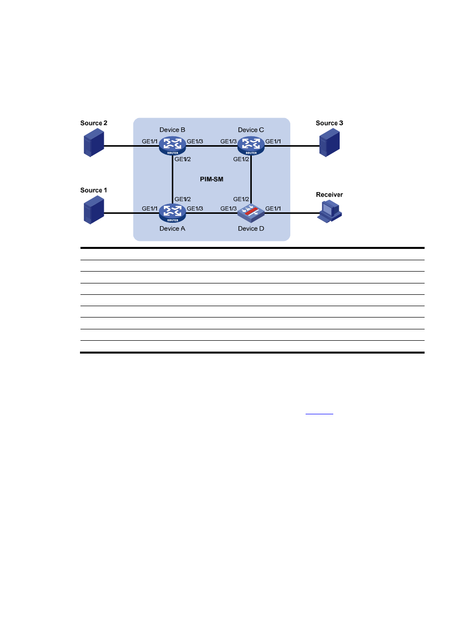
Source 1, Source 2, and Source 3 send multicast packets to multicast groups in the SSM group
range. It is required to configure the IGMP SSM mapping feature on Device D so that the receiver
host will receive multicast data from Source 1 and Source 3 only.
Network diagram
Figure 6 Network diagram for IGMP SSM mapping configuration
Device
Interface
IP address
Device
Interface
IP address
Source 1
—
133.133.1.1/24
Source 3
—
133.133.3.1/24
Source 2
—
133.133.2.1/24
Receiver
—
133.133.4.1/24
Device A
GE1/1
133.133.1.2/24
Device C
GE1/1
133.133.3.2/24
GE1/2
192.168.1.1/24
GE1/2
192.168.3.1/24
GE1/3
192.168.4.2/24
GE1/3
192.168.2.2/24
Device A
GE1/1
133.133.2.2/24
Device D
GE1/1
133.133.4.2/24
GE1/2
192.168.1.2/24
GE1/2
192.168.3.2/24
GE1/3
192.168.2.1/24
GE1/3
192.168.4.1/24
Configuration procedure
Step1
Configure IP addresses and unicast routing
Configure the IP address and subnet mask of each interface as per
. The detailed configuration
steps are omitted here.
Configure OSPF for interoperability among the devices. Ensure the network-layer interoperation in the
PIM-SM domain and dynamic update of routing information among the devices through a unicast routing
protocol. The detailed configuration steps are omitted here.
Step2
Enable IP multicast routing, enable PIM-SM on each interface, and enable IGMP and IGMP SSM
mapping on the host-side interface.
# Enable IP multicast routing on Device D, enable PIM-SM on each interface and enable IGMPv3 and
IGMP SSM mapping on GigabitEthernet 1/1.
[DeviceD] multicast routing-enable
[DeviceD] interface gigabitethernet 1/1
[DeviceD-GigabitEthernet1/1] igmp enable
[DeviceD-GigabitEthernet1/1] igmp version 3
[DeviceD-GigabitEthernet1/1] igmp ssm-mapping enable
[DeviceD-GigabitEthernet1/1] pim sm