Network diagram, Configuration procedure – H3C Technologies H3C SecPath F1000-E User Manual
Page 28
14
•
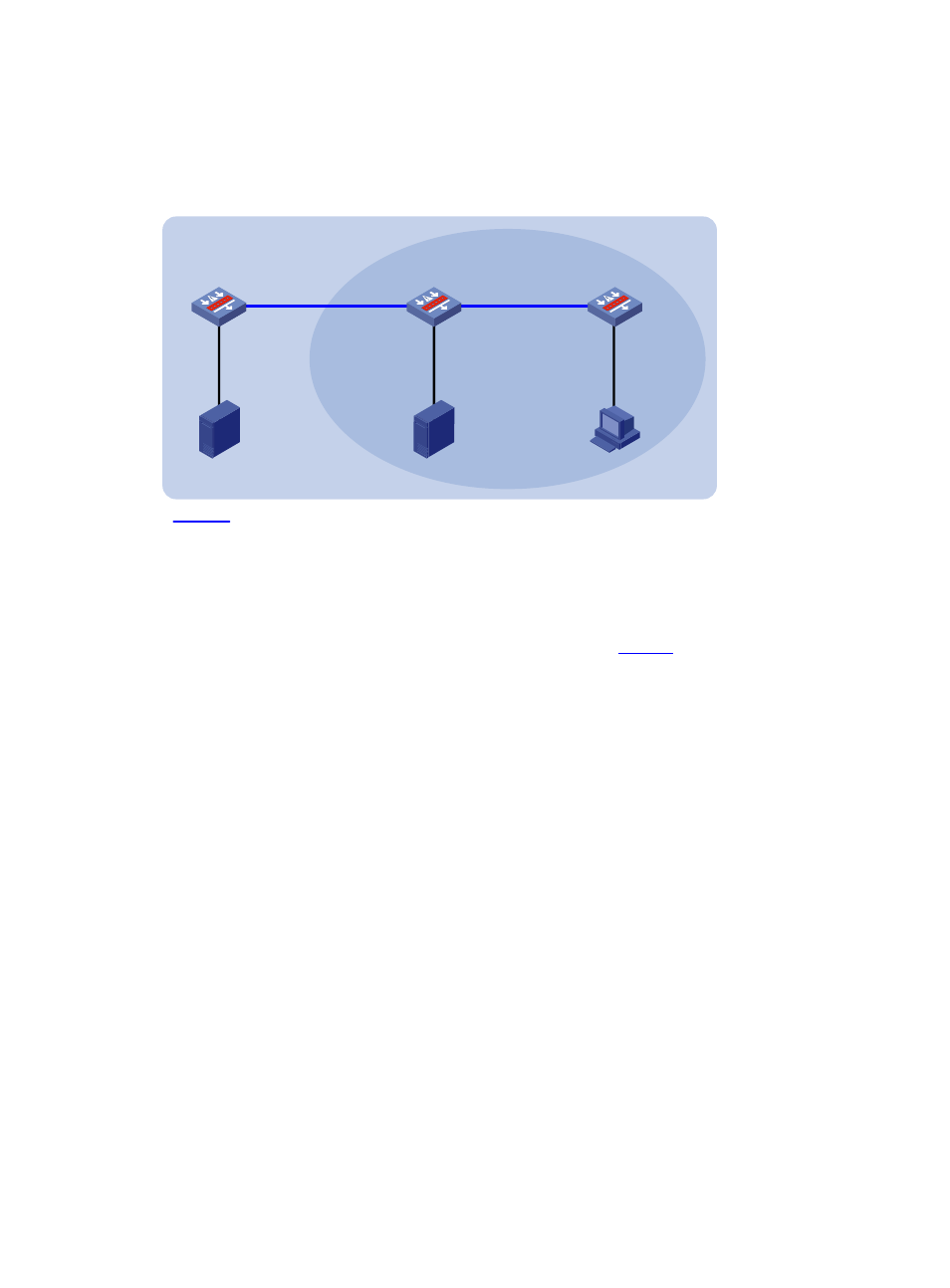
Perform the following configuration so that Receiver can receive multicast data from Source 2, which
is outside the OSPF domain.
Network diagram
Figure 6 Network diagram for creating an RPF route
Device A
Device B
Device C
GE0/2
30.1.1.2/24
GE0/2
20.1.1.2/24
GE0/2
20.1.1.1/24
GE0/3
30.1.1.1/24
Source 1
Source 2
Receiver
40.1.1.100/24
10.1.1.100/24
Multicast static route
GE0/1
40.1.1.1/24
GE0/1
10.1.1.1/24
OSPF domain
PIM-DM
50.1.1.100/24
GE0/1
50.1.1.1/24
Configuration procedure
Step1
Configure IP addresses and unicast routing
Configure the IP address and subnet mask for each interface as per
. The detailed configuration
steps are omitted here.
Enable OSPF on Device B and Device C. Ensure the network-layer interoperation among Device B and
Device C. Ensure that the devices can dynamically update their routing information by leveraging the
unicast routing protocol. The specific configuration steps are omitted here.
Step2
Enable IP multicast routing, and enable PIM-DM and IGMP
# Enable IP multicast routing on Device C, enable PIM-DM on each interface, and enable IGMP on
GigabitEthernet 0/1.
[DeviceC] multicast routing-enable
[DeviceC] interface gigabitethernet 0/1
[DeviceC-GigabitEthernet0/1] igmp enable
[DeviceC-GigabitEthernet0/1] pim dm
[DeviceC-GigabitEthernet0/1] quit
[DeviceC] interface gigabitethernet 0/2
[DeviceC-GigabitEthernet0/2] pim dm
[DeviceC-GigabitEthernet0/2] quit
# Enable IP multicast routing on Device A and enable PIM-DM on each interface.
[DeviceA] multicast routing-enable
[DeviceA] interface gigabitethernet 0/1
[DeviceA-GigabitEthernet0/1] pim dm
[DeviceA-GigabitEthernet0/1] quit