Configuration procedure – H3C Technologies H3C SecPath F1000-E User Manual
Page 141
45
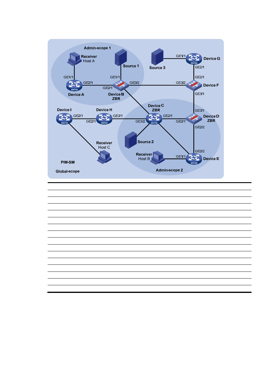
Figure 12 Network diagram for PIM-SM admin-scope zone configuration
GE2/2
GE3/1
G
E1
/1
GE2/1
G
E1/
1
GE3/1
Device
Interface
IP address
Device
Interface
IP address
Device A
GE1/1
192.168.1.1/24
Device D
GE2/1
10.110.4.2/24
GE2/1
10.110.1.1/24
GE2/2
10.110.7.1/24
Device B
GE1/1
192.168.2.1/24
GE3/1
10.110.8.1/24
GE2/1
10.110.1.2/24
Device
E
GE1/1
192.168.4.1/24
GE3/1
10.110.2.1/24
GE2/1
10.110.5.2/24
GE3/2
10.110.3.1/24
GE2/2
10.110.7.2/24
Device C
GE1/1
192.168.3.1/24
Device F
GE2/1
10.110.9.1/24
GE2/1
10.110.4.1/24
GE3/1
10.110.8.2/24
GE2/2
10.110.5.1/24
GE3/2
10.110.3.2/24
GE3/1
10.110.2.2/24
Device
G
GE1/1
192.168.5.1/24
GE3/2
10.110.6.1/24
GE2/1
10.110.9.2/24
Device H
GE2/1
10.110.10.1/24
Source 1
—
192.168.2.10/24
GE3/1
10.110.6.2/24
Source
2
— 192.168.3.10/24
Device I
GE1/1
192.168.6.1/24
Source 3
—
192.168.5.10/24
GE2/1
10.110.10.2/24
Configuration procedure
Step1
Configure IP addresses and unicast routing
Configure the IP address and subnet mask for each interface as per
. The detailed configuration
steps are omitted here.